Automatic fuelling device

A technology of automatic refueling and oil pressure, applied in the directions of engine components, engine lubrication, lubrication pumps, etc., can solve the problems of high cost, multi-function equipment, complex structure, etc., and achieve the effect of low cost, easy manufacturing and reasonable structure

Inactive Publication Date: 2008-09-17
SHANGHAI UNIV +1
View PDF0 Cites 11 Cited by
  • Summary
  • Abstract
  • Description
  • Claims
  • Application Information

AI Technical Summary

Problems solved by technology

[0002] The existing automatic refueling system generally uses a gear pump driven by a micro motor to inject grease into the pipeline system, and then distributes the lubricating oil to each refueling lubrication point in proportion through the oil volume distributor. The oil injection period and oil injection volume can be arbitrary. Adjustment, and has the function of working status and liquid level monitoring, the equipment has many functions, complex structure and high cost

Method used


Image

  • Automatic fuelling device
  • Automatic fuelling device
  • Automatic fuelling device

Examples


Embodiment Construction

[0015] A preferred embodiment of the present invention is described as follows in conjunction with accompanying drawing:

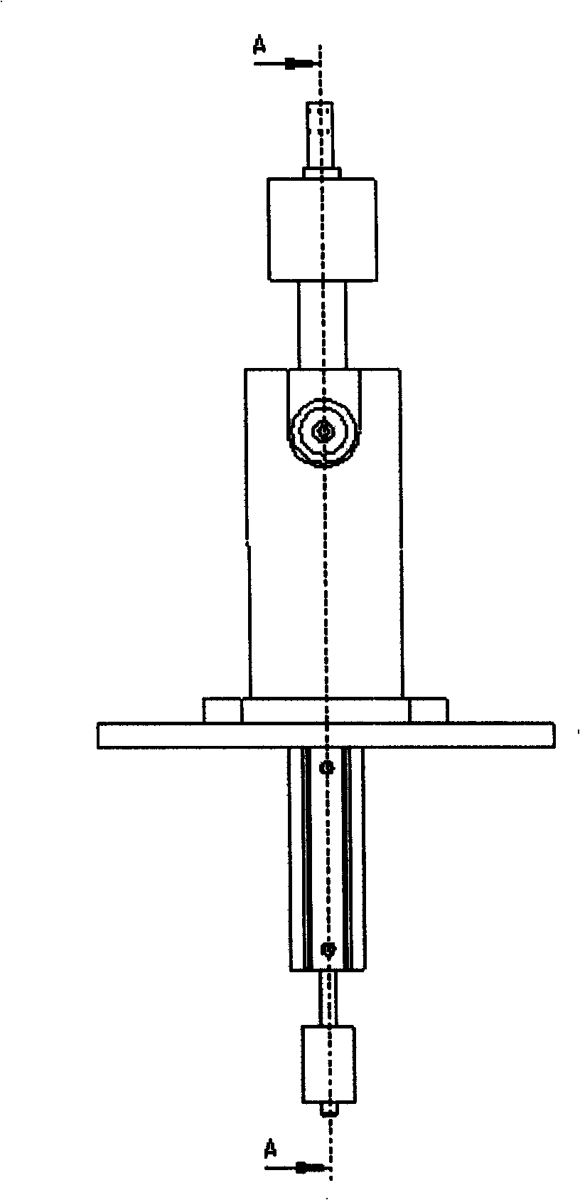
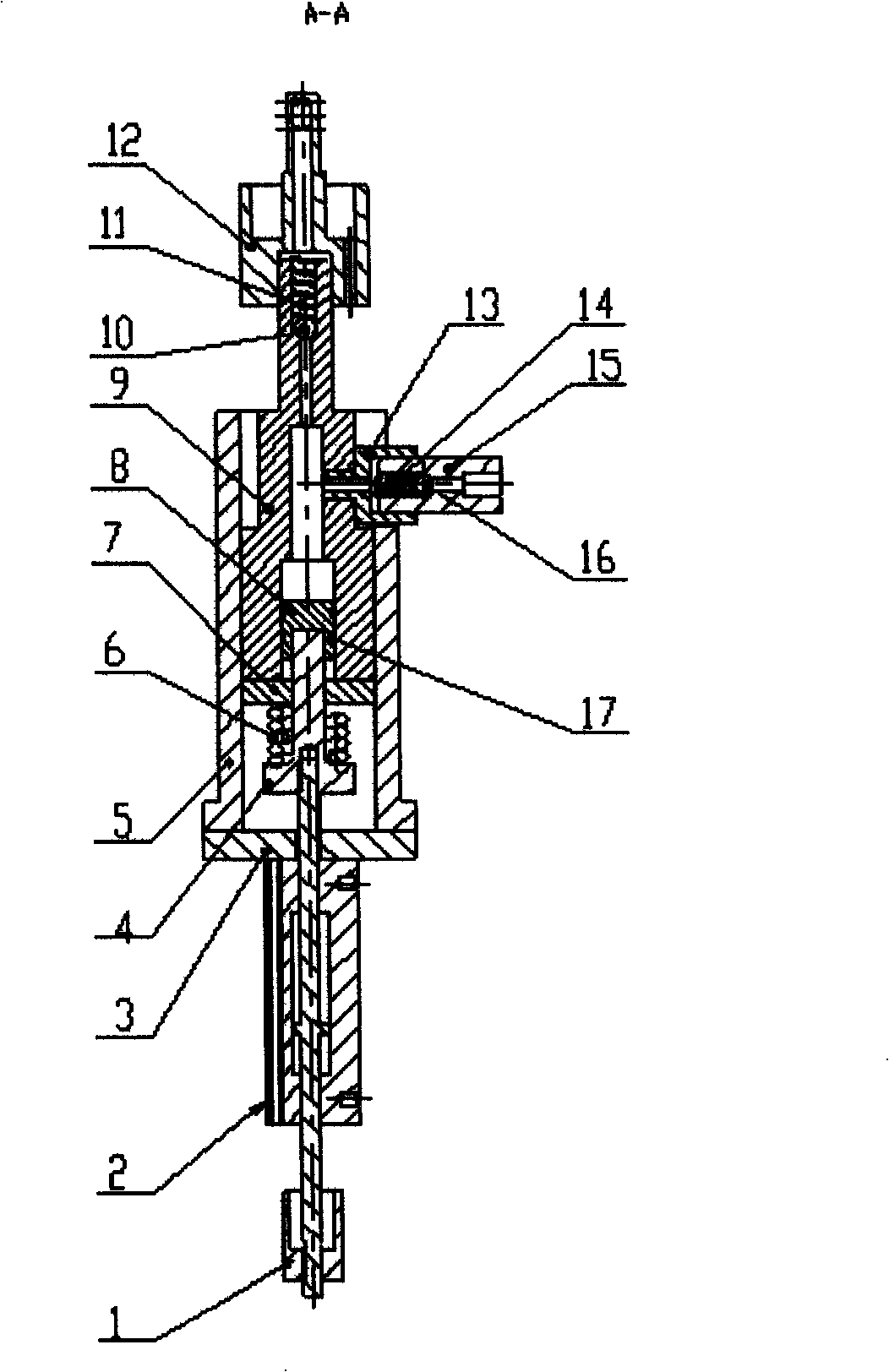
[0016] see figure 1 and figure 2 , the automatic refueling device includes an oil pressure cylinder 9 and an oil pressure piston 8 matched therewith, and a piston connecting rod 4 connected with the oil pressure piston 8 . It is characterized in that the oil outlet of the hydraulic cylinder 9 is connected to an oil outlet nozzle 12 through an oil outlet check valve, and the oil inlet is connected to the oil inlet pipe joint 15 through an oil inlet check valve; the outer end of the oil pressure piston 8 Connected to a matching piston rod of an actuating cylinder 2.

[0017] For further detailed structure see figure 2 , the adjusting screw sleeve 1 is fixed on the piston rod end of the cylinder 2 through threads; the cylinder 2 is fixedly connected with the mounting plate 3 through bolts; the piston connecting rod 4 is connected with the other piston ro...


PUM


Abstract

The invention relates to an automatically-oiling device, which comprises an oil pressure cylinder body, an oil pressure piston matched with the oil pressure cylinder body, and a piston rod connected with the oil pressure piston. The oil outlet of the oil pressure cylinder body is connected with an oil outlet spout, the oil inlet is connected with an inlet connector through an oil inlet check valve, and the outer end of the oil pressure piston is connected with a piston rod matched with a movement cylinder. The automatically-oiling device can realize self-oiling and control fuel charge. The automatically-oiling device has the advantages of reasonable, compact and reasonable structure, low cost, and convenient use. Furthermore, the automatically-oiling device is suitable for oiling various mechanical components.

Description

technical field [0001] The patent of the present invention relates to an automatic refueling device with controllable oil quantity. Background technique [0002] The existing automatic refueling system generally uses a gear pump driven by a micro motor to inject grease into the pipeline system, and then distributes the lubricating oil to each refueling lubrication point in proportion through the oil volume distributor. The oil injection period and oil injection volume can be arbitrary. Adjustment, and has the function of working status and liquid level monitoring. The equipment has many functions, complex structure and high cost. Contents of the invention [0003] The object of the present invention is to provide an improved automatic refueling device aimed at the defects of the prior art, which can realize refueling automatically and control the amount of refueling, and has a simple structure and is easy to use. [0004] To achieve the above object, the present invention...

Claims


Application Information

Patent Timeline
Patent Type & Authority Applications(China)
IPC IPC(8): F16N13/16
Inventor 张海洪刘宗阳郭乐意沈立红杜向栋王卫峰周涛
Owner SHANGHAI UNIV
Why Eureka
Try Eureka