Pile foundation tower-footing impedance measuring apparatus and its method
A technology of grounding impedance and measuring device, which is applied in the direction of grounding resistance measurement, measuring device, measuring electric variable, etc.
- Summary
- Abstract
- Description
- Claims
- Application Information
AI Technical Summary
Problems solved by technology
Method used
Image
Examples
Embodiment 1
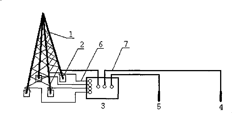
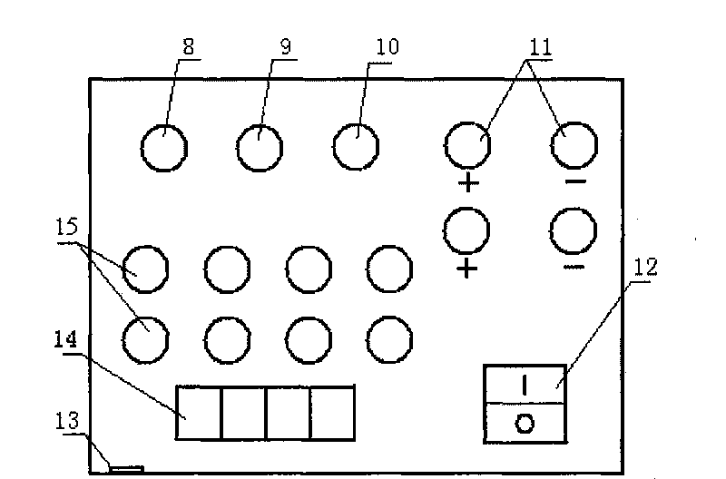
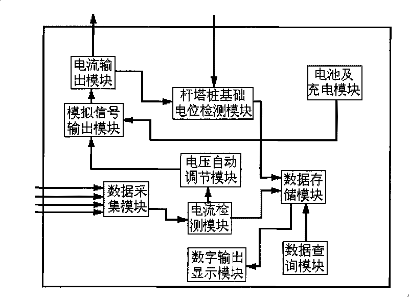
[0055] Figure 1-5 As shown, a pile foundation pole tower grounding impedance measurement device mainly includes auxiliary measuring electrodes, high-precision soft belt type Rogowski coil current sensor 2, pole tower grounding impedance measuring instrument 3 and so on. Its auxiliary measuring electrodes are a current electrode 4 and a voltage electrode 5, each electrode is a steel rod with a length of 25 cm and a diameter of 1 cm, and the current electrode 4 is inserted into the ground at a distance of 45 m from the pole tower 1. The current electrode port 9 of the measuring instrument 3 is connected to form a current loop for measurement; the voltage electrode 5 is inserted into the same side of the current electrode 4 and the distance from the pole tower is 0.6 times the distance from the current electrode 4, and is connected to the measurement through the wire 7 The voltage pole terminal 10 of the instrument is connected. There are four high-precision soft-band Rogowski ...
Embodiment 2
[0057] A grounding impedance measuring device for a pile foundation pole tower, same as embodiment 1. Its characteristics are: each electrode is a steel rod with a length of 20cm and a diameter of 0.8cm, the current pole 4 is inserted into the ground at a distance of 40m from the tower 1, and the voltage pole 5 is inserted on the same side of the current pole 4 and at a distance from the pole tower 1. In the ground whose distance is 0.5 times of the distance between the current poles 4, each coil is evenly and densely wound with an enamelled copper wire 17 with a wire diameter of 0.2 mm on six permeable magnetic cores 16 with a diameter of 1 cm and a length of 4 cm. The magnetically conductive core 16 of the enamelled copper wire 17 is filled into an open annular plastic hose 18 with an inner diameter of 1.5 cm. The inner diameter of the whole coil is 8 cm and the number of turns is 100 turns. The analog signal output module adjusts and outputs a step frequency of 1Hz, the sig...
Embodiment 3
[0059] A grounding impedance measuring device for a pile foundation pole tower, same as embodiment 1. Its characteristics are: each electrode is a steel rod with a length of 30cm and a diameter of 1.2cm, the current pole 4 is inserted into the ground at a distance of 60m from the tower 1, and the voltage pole 5 is inserted on the same side of the current pole 4 and the distance from the tower 1 In the ground where the current pole 4 is arranged at a distance of 0.6 times, each coil is evenly wound with an enameled copper wire 17 with a wire diameter of 1 mm on 26 permeable magnetic cores 16 with a diameter of 1.8 cm and a length of 6 cm. The magnetic core 16 of the enamelled copper wire 17 is filled into an open annular plastic hose 18 with an inner diameter of 2 cm. The inner diameter of the entire coil is 50 cm and the number of turns is 1300 turns. The analog signal output module adjusts and outputs a step frequency of 1 Hz , The signal frequency is 150Hz different frequenc...
PUM
 Abstract
Description
Claims
Application Information
 - R&D
- Intellectual Property
- Life Sciences
- Materials
- Tech Scout
- Unparalleled Data Quality
- Higher Quality Content
- 60% Fewer Hallucinations
Browse by: Latest US Patents, China's latest patents, Technical Efficacy Thesaurus, Application Domain, Technology Topic, Popular Technical Reports.
© 2025 PatSnap. All rights reserved.Legal|Privacy policy|Modern Slavery Act Transparency Statement|Sitemap|About US| Contact US: help@patsnap.com


