Winder feeding rack

A technology of winding machine and material rack, applied in the field of material rack, can solve the problems of back up, different tightness of the outlet, deviation and so on.

Inactive Publication Date: 2011-07-20
慈溪市大华电器有限公司
View PDF0 Cites 0 Cited by
  • Summary
  • Abstract
  • Description
  • Claims
  • Application Information

AI Technical Summary

Problems solved by technology

The defect of this traditional material rack is: because there is no partition on the cylinder body to isolate the copper strips, the material rack is prone to interlacing and back-up during the outgoing line process, and because each The tightness of the coiled copper tape is different, resulting in different tightness of the outgoing wire during the winding process, which cannot be adjusted and deviates

Method used


Image

  • Winder feeding rack
  • Winder feeding rack
  • Winder feeding rack

Examples


Embodiment Construction

[0016] The present invention will be further described below in conjunction with the accompanying drawings.

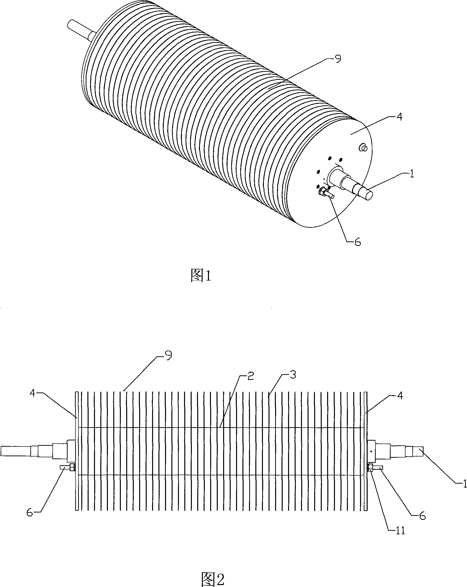
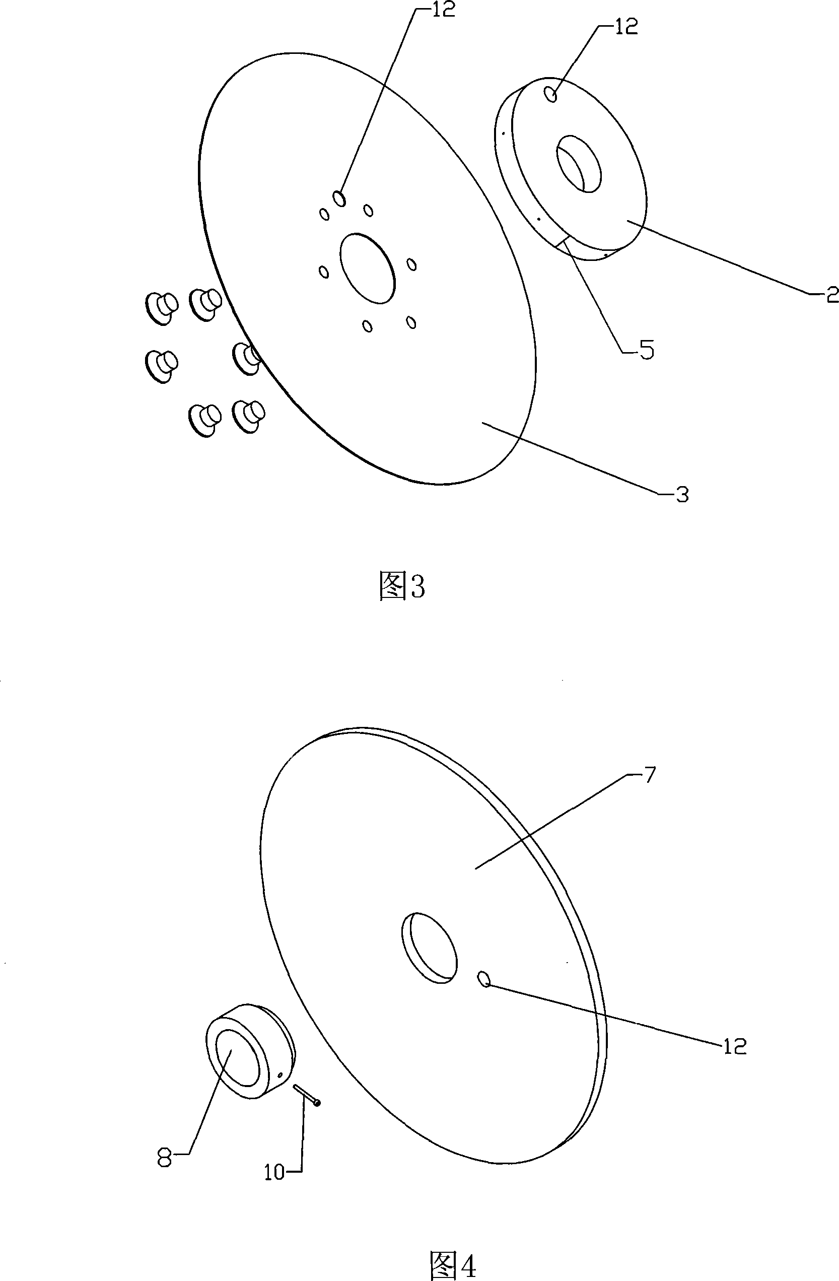
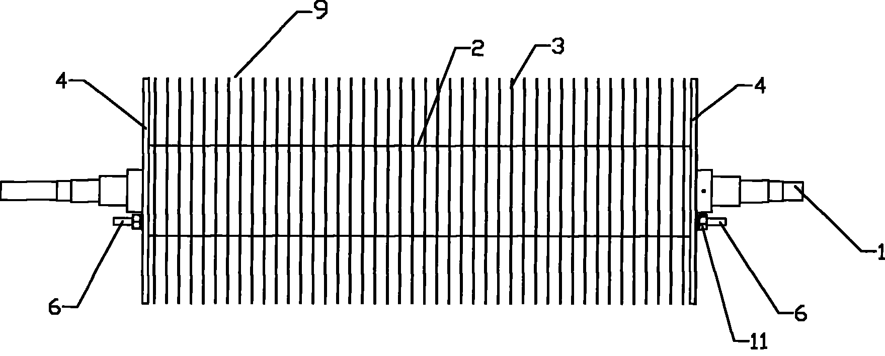
[0017] see Figure 1-4 : winding machine material rack, including main shaft 1, described main shaft 1 is installed on the winding machine frame by bearing, and described main shaft 1 is sleeved with winding disc 2 and circular partition 3 arranged at intervals Composed winding main body 9, the two ends of said main body have clamping device 4, and described clamping device 4 is connected with main shaft 1, and the diameter of described separator 3 is larger than the diameter of described winding disc 2, and described The arc surface of the winding reel 2 has a connecting part for fixing the winding end, and the clamping device 4 is integrally connected in series with each winding reel 2 and partition plate 3 of the main body through a connecting rod 6 .

[0018] The connecting portion is a slot 5 extending inward along the arc surface of the reel 2 .

[0019] The cl...


PUM


Abstract

The invention relates to a coil winding machine material rest, comprising a main shaft, the main shaft is installed on a frame of the coil winding machine through a bearing, the main shaft is sleeved with a coil winding main body composed of coil winding discs and circular clapboards that are mutually arrayed at interval, two ends of the main body are provided with clamping devices which are connected with the main shaft, diameter of the clapboards is larger than that of the coil winding discs, a connecting part for fixing the coil winding heads are provided on a circular arc face of the coilwinding discs, the clamping devices is in series connection with each coil winding disc and clapboard of the main body through a connection rod. The invention provides a coil winding machine materialrest which does not protrude and mutually interlace, and can automatically adjust the degree of tightness and actively correct errors while delivering the coils.

Description

(1) Technical field [0001] The invention relates to a material rack on a winding machine, in particular to a winding machine material rack for conveying coil copper strips. (2) Technical background [0002] The material rack on the existing winding machine has an integrated cylindrical structure, and no partition is provided on the cylindrical body to isolate the adjacent coils of copper strips. The coil winding process has two processes: coiling and winding. When coiling, several rolls of copper strips are wound side by side on the barrel of the material rack. After the copper strips are coiled, they enter the coil winding process. The wire ends of each roll of copper strip are drawn to the winding die at the head of the winding machine, and the wire ends of each roll of copper tape are welded side by side on a copper bar fixed on the winding die, and then the winding die is rotated, the material The wire is drawn out, and the copper strip is wound on the winding die layer...

Claims


Application Information

Patent Timeline
Patent Type & Authority Patents(China)
IPC IPC(8): H01F41/06H01F41/096
Inventor 王立华
Owner 慈溪市大华电器有限公司
Why Eureka
Try Eureka