
Method for predicting antenna electric performance based on simulated distortion reflective side

A technology of performance prediction and reflective surface, applied in antennas, electrical components, electrical digital data processing, etc., can solve the problems of not reflecting the real influence relationship of the antenna structure and difficult structural deformation.

Inactive Publication Date: 2012-10-24
XIDIAN UNIV
View PDF0 Cites 0 Cited by
  • Summary
  • Abstract
  • Description
  • Claims
  • Application Information

AI Technical Summary

Problems solved by technology

This method only assumes that the deformation of the reflecting surface satisfies a certain trigonometric function distribution, but it is difficult to use a specific function to give the structural deformation in practice.
At the same time, the comprehensive analysis of the electromechanical performance of this method is based on the assumption of the shape of the structural deformation, which cannot reflect the real influence relationship between the structural deformation of the antenna and the electrical performance of the antenna.

Method used


Image

  • Method for predicting antenna electric performance based on simulated distortion reflective side
  • Method for predicting antenna electric performance based on simulated distortion reflective side
  • Method for predicting antenna electric performance based on simulated distortion reflective side

Examples


Embodiment Construction

[0061] The present invention will be described in further detail below with reference to the accompanying drawings.

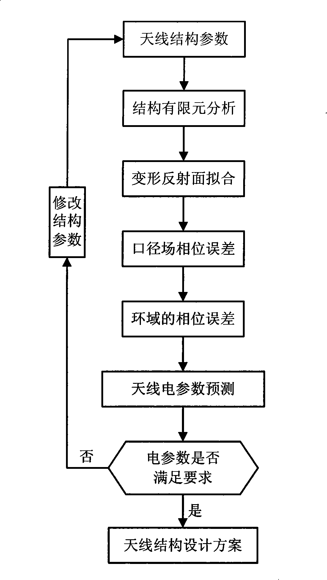
[0062] refer to figure 1 , the concrete steps of the present invention are as follows:

[0063] Step 1: Establish a finite element model of the reflector antenna.

[0064] According to the basic parameters of antenna diameter D, focal length f, reflective panel, radiation beam, ring beam, and central body, the finite element model of the antenna structure is determined, and the theoretical coordinates P(x i ,y i ,z i ). At the same time, determine the coordinate h of the vertex of the reflective surface in the model coordinate system, which is generally the height in the Z direction.

[0065] Step 2: Analyze the finite element model to obtain the information of the sampled nodes after deformation.

[0066] Using finite element software, the finite element analysis of the antenna reflector structure is carried out under different working conditions of self...


PUM


Abstract

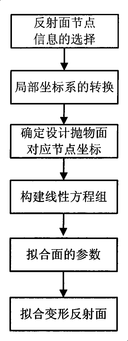
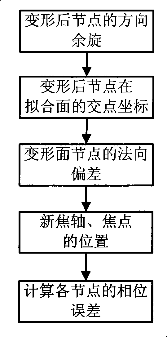
The present invention provides a prediction method of the antenna electrical property based on the fitting deformation reflector, mainly resolving the problem of electro-mechanical separation in the antenna design. The method includes following steps: obtaining a node displacement after the deforming of the reflector based on the finite element analysis of the antenna structure; designing the space position relationship of the coordination and the deformed coordinate according to the theory of the reflector node, processing fit to the deformed reflector; calculating the normal error of the antenna surface and the phase error caused by the normal error by utilizing the fitting reflector; calculating antenna far fields electric field distribution according to the amplitude and the phase parameter of the antenna aperture; calculating antenna far fields electrical pattern according to the antenna far fields electric field distribution, obtaining the electrical parameter from the directionpattern, realizing the electrical property prediction of the reflector antenna structure displacement field and the electromagnetic field coupling. The invention can guide the structure design of theantenna, and comprehensively analyzes and assesses the antenna electromechanical properties under different conditions.

Description

technical field [0001] The invention belongs to the technical field of antennas, in particular to a method for predicting electrical properties of antennas based on fitting deformed reflecting surfaces. It is used to guide the structural design, performance simulation analysis and evaluation of the antenna. Background technique [0002] With the development of communication and radio astronomy, planar antennas are developing towards high-frequency bands and large apertures. The large planar antenna structure is a typical mechatronic structure, and its mechanical and electrical properties influence and restrict each other. In engineering, electrical engineers propose mechanical structure design requirements, while structural engineers can only assign the design accuracy of each component based on experience. As a result, there are two situations. One is that the latter has exhausted all methods and used the best processing equipment and methods, but still cannot meet the re...

Claims


Application Information

Patent Timeline
Patent Type & Authority Patents(China)
IPC IPC(8): H01Q19/10G06F17/00G06F17/50
Inventor 段宝岩王从思李鹏张福顺郑飞保宏王伟仇原鹰陈光达黄进朱敏波宋立伟
Owner XIDIAN UNIV
Learn More