Supercharge Your Innovation With Domain-Expert AI Agents!

Condensation water drainage configuration used for evaporator unit

A technology for evaporators and condensed water, applied in the direction of preventing condensed water, household refrigeration equipment, applications, etc., can solve heavy and difficult problems in production and assembly

Inactive Publication Date: 2008-09-24
CARRIER CORP
View PDF1 Cites 6 Cited by
  • Summary
  • Abstract
  • Description
  • Claims
  • Application Information

AI Technical Summary

Problems solved by technology

In manufacturing these units, especially as these units become larger, the production and assembly of the various components becomes onerous and tricky

Method used


Image

  • Condensation water drainage configuration used for evaporator unit
  • Condensation water drainage configuration used for evaporator unit
  • Condensation water drainage configuration used for evaporator unit

Examples


Embodiment Construction

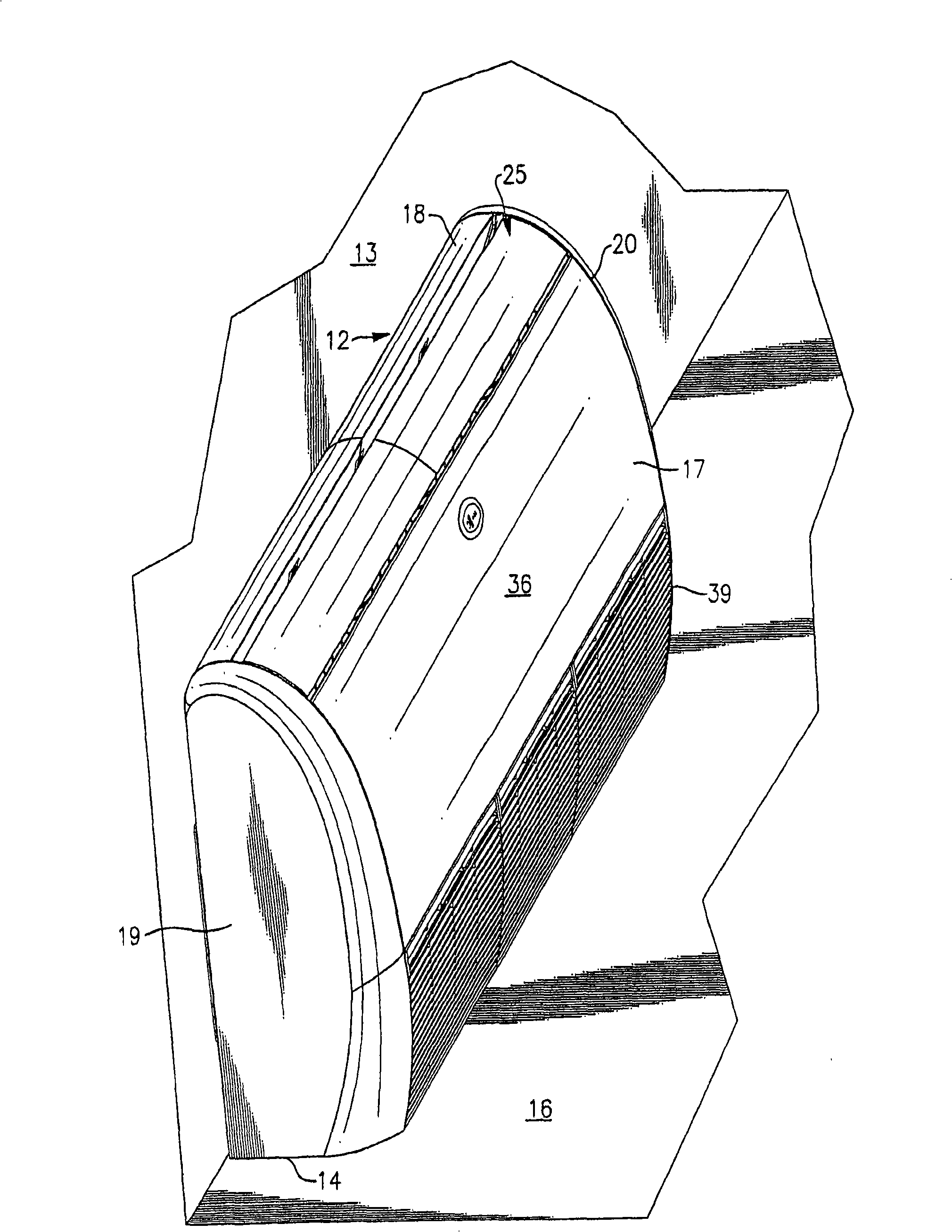
[0025] The invention is applicable to the evaporator unit 11, the evaporator unit 11 in figure 1 is shown mounted in a generally vertical orientation with its rear side 12 mounted against a wall 13 and its bottom side 14 mounted adjacent a floor 16 . Although, as will be described hereinafter, the unit is also designed to be alternatively mounted in a generally horizontal position with its rear side 12 resting on the ceiling and its bottom side 14 against the side walls 13, But it will now be described in the case of a vertical orientation (as shown). Thus, in addition to a rear side 12 and a bottom side 14 , the evaporator unit 11 has a front side 17 , a top side 18 , a left side 19 and a right side 20 .

[0026] On the front side 17 of the evaporator unit 11 there is a front panel 36 behind which is an evaporator compartment comprising an evaporator coil. Below the front panel 36 is a grille structure 39 and behind the grille structure 39 is an air intake that is in fluid ...


PUM


Abstract

An evaporator unit which is adaptable to be installed in either a horizontal or a vertical orientation is provided with a single drain pan which will accommodate either installation. The drain pan is a composite of an inner and outer shell and includes a pair of troughs with one trough being adapted to collect the condensate in a vertical orientation and the other trough being adapted to collect the condensate in a horizontal orientation. A drainage fixture is disposed at one end of the drain pan for receiving condensate flow from the drain pan and draining the condensate therefrom. The drainage fixture includes an inlet channel associated with each trough and a baffle for preventing the condensate from blowing past the drainage fixture.

Description

technical field [0001] The present invention relates generally to evaporator units for air conditioning systems, and more particularly to condensate drain arrangements for condensate drain pans. Background technique [0002] In many commercial air conditioning, heating and ventilation systems, conditioned air is discharged into interior spaces through air distribution or conditioning units. For example, one common type of air conditioning system, often referred to as a split system, includes separate indoor and outdoor units. The outdoor unit includes a compressor, a heat exchanger and a fan. The indoor unit includes a heat exchanger and a fan and is called an evaporator unit. In operation, the indoor fan draws air into the evaporator unit through the inlet of the evaporator unit, and forces the air to pass over the heat exchanger and then out of the evaporator unit through an outlet opening in the evaporator. [0003] The outdoor fan draws outdoor air into the outdoor un...

Claims


Application Information

Patent Timeline
IPC IPC(8): F25D21/14F24F1/0063
CPCF24F13/222F24F2001/0037F28F17/005F24F2001/004F24F1/0007F24F1/0047F24F1/005F24F1/0063F24F1/00F24F13/22F25D21/14
Inventor L·D·L·莫雷斯
Owner CARRIER CORP
Features
  • R&D
  • Intellectual Property
  • Life Sciences
  • Materials
  • Tech Scout
  • Unparalleled Data Quality
  • Higher Quality Content
  • 60% Fewer Hallucinations
Learn More