Split type wing

A composite and composite wing technology, applied in the field of aircraft wings, can solve problems such as the inability to smoothly transition to the state of level flight, the inability to meet the needs of use, and the large wind resistance of the wing, so as to eliminate unbalanced disturbance torque and ensure lateral stability. The effect of stability and stress dispersion

Inactive Publication Date: 2008-10-01
穆骞
View PDF0 Cites 14 Cited by
  • Summary
  • Abstract
  • Description
  • Claims
  • Application Information

AI Technical Summary

Problems solved by technology

[0002] At present, various existing vertical take-off and landing aircraft that use propellers, counter-rotating propellers, or ducted fans as tilting power devices all install these tilting power devices on the wingtips of the wings, or together with the entire wing Tilting together, this causes a very large unbalanced moment during vertical take-off and landing, which is prone to instability and rolls, or the wind resistance of the entire wing is particularly large during transitional flight, making it impossible to smoothly transition to level flight status, which is one of the main reasons why such aircraft have had little success so far
Therefore, the wing configuration of the existing vertical take-off and landing aircraft cannot meet the needs of people.

Method used


Image

  • Split type wing

Examples


Embodiment Construction

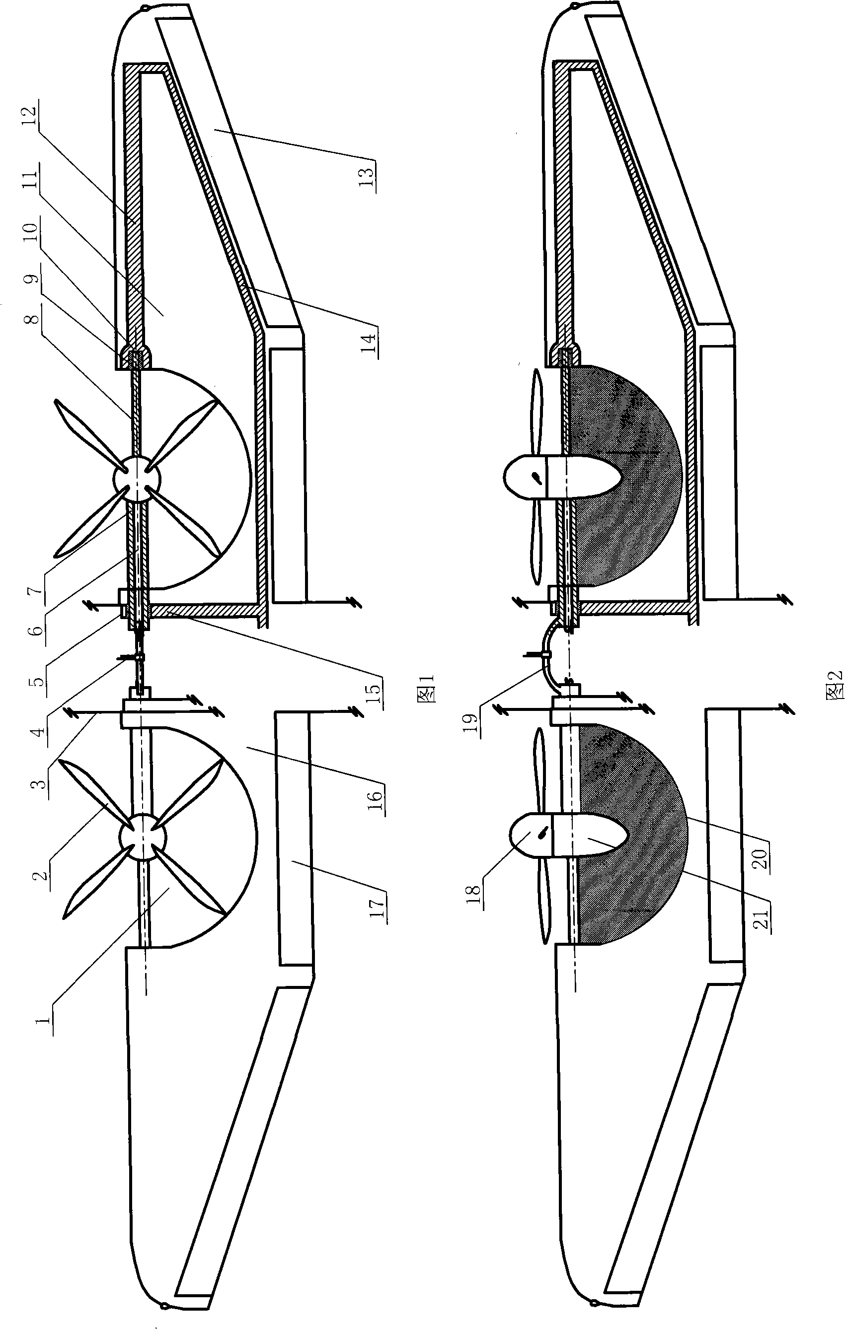
[0010] The cracked composite wing of the present invention comprises a wing main body 16, the wing main body 16 is connected with the main load-bearing frame 15 of the body, and the tiltable section of the main spar is movably installed on the main load-bearing frame 15 of the body, and the main spar can be tilted The two ends of the section are movably connected with the non-tilting section 12 of the main spar, and a split composite airfoil 20 is respectively installed on the left and right sides of the tiltable section of the main spar, and a group of tilting power devices are arranged in front of each split composite airfoil 20 . The wing main body 16 is provided with a cracked through space with the same shape as the cracked composite airfoil 20. The cracked composite airfoil 20 is located in the cracked through space, and the left and right sides of the wing main body 16 are fixedly connected to the outer wing with a large span. When taking off vertically, the tiltable se...


PUM


Abstract

The invention discloses a cracking combined type wing which comprises a wing body which is connected with the main force-bearing frame of an airframe. The main force-bearing frame of the airframe is moveably provided with the rotatable section of a main wing beam and the two ends of the rotatable section of the main wing beam are connected with the unrotatable section of the main wing beam. The left and right sections of the rotatable section of the main wing beam are respectively provided with a cracking combined aerofoil which is provided with a set of rotating power devices at the front part. The cracking combined type aerofoil is positioned in a cracking communicating space of the wing body while the shape of the space is the same as that of the aerofoil. The left side and the right side of the wing body are fixedly connected with an external wing with a large span. The cracking combined type wing can minimize unbalanced moments caused during the vertical take-off and landing of an aircraft and resistance against the wind of the wing during the transition flight, meanwhile, the whole wing, more particularly the external wing with large span, remains stationary horizontally all the time, thus ensuring the stability of the aircraft during the vertical take-off and landing as well as smooth transition to the level flight so as to meet the user requirements.

Description

technical field [0001] The invention relates to an aircraft wing, in particular to a split composite wing. Background technique [0002] At present, various existing vertical take-off and landing aircraft that use propellers, counter-rotating propellers, or ducted fans as tilting power devices all install these tilting power devices on the wingtips of the wings, or together with the entire wing Tilting together, this causes a very large unbalanced moment during vertical take-off and landing, which is prone to instability and rolls, or the wind resistance of the entire wing is particularly large during transitional flight, making it impossible to smoothly transition to level flight This is also one of the main reasons why this type of aircraft has had little success so far. Therefore, the wing configuration of the existing vertical take-off and landing aircraft cannot meet the needs of people. Contents of the invention [0003] The purpose of the present invention is to p...

Claims


Application Information

Patent Timeline
Patent Type & Authority Applications(China)
IPC IPC(8): B64C27/22
CPCB64C29/0033
Inventor 穆骞
Owner 穆骞
Why Eureka
Try Eureka