Louver type cracking composite wing

A louver-type, composite wing technology, applied in the field of aircraft wings, can solve the problems of unsatisfactory use requirements, large wing wind resistance, large unbalanced moment, etc., and achieve small moment load, stress dispersion, and solid load-bearing structure Effect

Inactive Publication Date: 2009-03-11
穆骞
View PDF0 Cites 1 Cited by
  • Summary
  • Abstract
  • Description
  • Claims
  • Application Information

AI Technical Summary

Problems solved by technology

[0002] At present, various existing vertical take-off and landing aircrafts that use propellers, counter-rotating propellers, rotors or ducted fans as tilting power devices all install these tilting power devices on the wingtips of the wings, or together with the entire The wings are tilted together, which results in a very large unbalanced moment during vertical take-off and landing, which is prone to instability and rolls, or the wind resistance of the entire wing is particularly large during transitional flight, making it impossible to transition smoothly to This is one of the main reasons why this type of aircraft has seldom been successful so far.
Therefore, the wing configuration of the existing vertical take-off and landing aircraft cannot meet the needs of people.

Method used


Image

  • Louver type cracking composite wing
  • Louver type cracking composite wing
  • Louver type cracking composite wing

Examples


Embodiment Construction

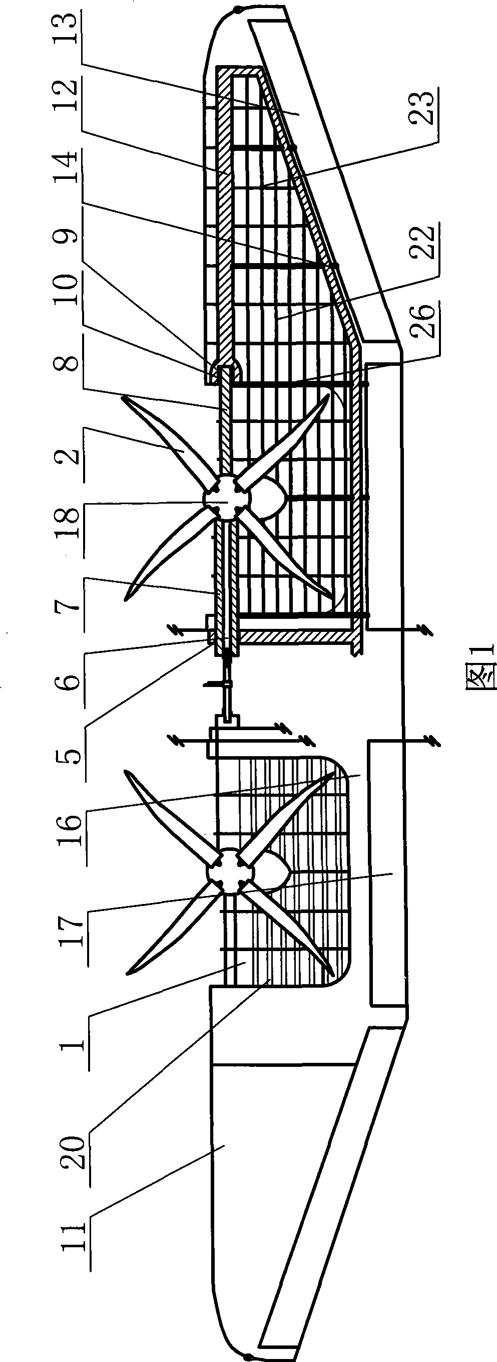
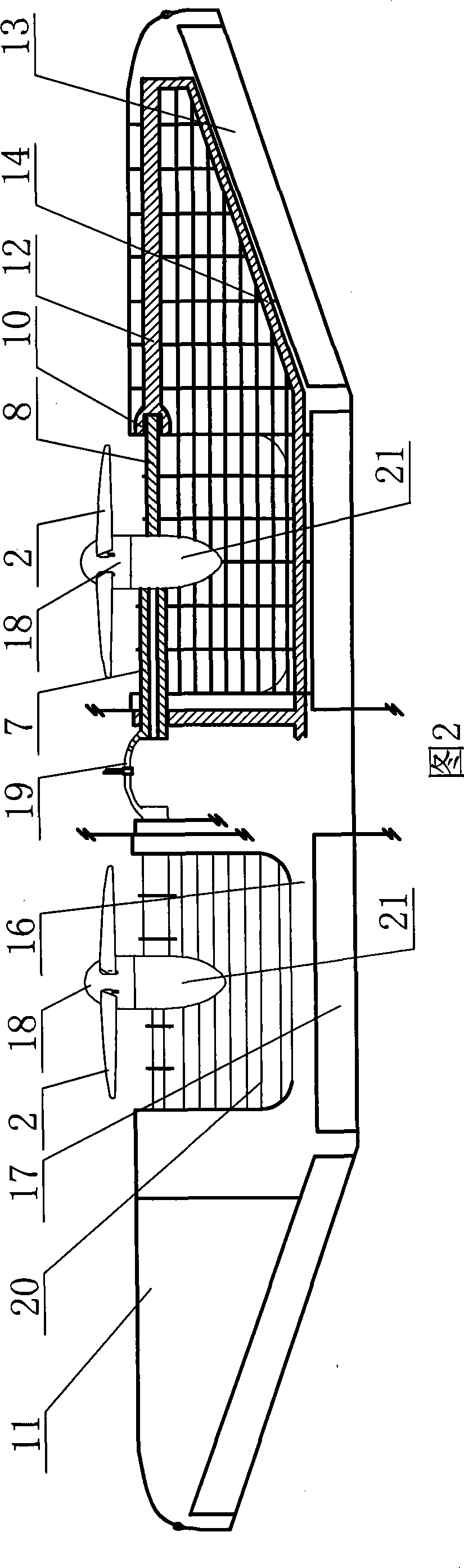
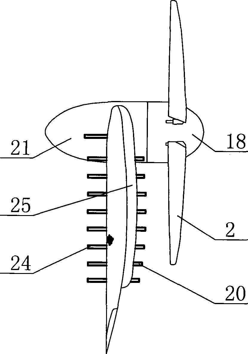
[0010] The louver type split composite wing of the present invention comprises a wing main body 16, a main spar and a rear spar 14 are arranged in the wing main body 16, and the main spar, the rear spar 14, long stringers 22 and wing ribs 23 etc. are jointly connected to form the main wing The main load-bearing structure of the beam, the main spar is composed of the tiltable section of the main spar and the non-tiltable section 12, and the tiltable section of the main spar can be tilted relative to the non-tiltable section 12; The frame 15 is fixedly connected, two penetrating spaces 1 can be symmetrically provided on the main wing 16, two sets of tilting power devices are installed on the tiltable section of the main spar, and a set of louvered cracked composite skin is installed in each penetrating space 1 , the louver-type cracking composite skin is composed of an upper louver-type cracking composite skin 20 and a lower louver-type cracking composite skin 24, and the upper l...


PUM


Abstract

The invention discloses a shutter-typed cracking composite wing, comprising a wing mainbody which is internally provided with a main wing beam and a rear wing beam; the main wing beam consists of an inclinable section and a non-inclinable section which are connected with each other; the wing mainbody is connected with an aircraft main bearing frame; the left side and the right side of the wing mainbody are respectively provided with two through spaces; the inclinable section of the main wing beam is provided with two groups of inclined power devices; each through space is respectively provided with a group of shutter-typed cracking composite envelope which consists of an upper shutter-typed cracking composite envelope and a lower shutter-typed cracking composite envelope; the upper shutter-typed cracking composite envelope and the lower shutter-typed cracking composite envelope are respectively connected with the wing mainbody. The wing leads the unbalanced moment during the vertical lifting of the aircraft and the wind-facing resistance during the transitional flying of the aircraft to be reduced to the minimum; meanwhile, the whole wing, especially for the external wing of the large wing keeps horizontal and still fixedly all the time, thus ensuring the stability during the vertical lifting of the aircraft and successful transition to the flat flying state.

Description

technical field [0001] The invention relates to an aircraft wing, in particular to a louver type split composite wing. Background technique [0002] At present, various existing vertical take-off and landing aircrafts that use propellers, counter-rotating propellers, rotors or ducted fans as tilting power devices all install these tilting power devices on the wingtips of the wings, or together with the entire The wings are tilted together, which results in a very large unbalanced moment during vertical take-off and landing, which is prone to instability and rolls, or the wind resistance of the entire wing is particularly large during transitional flight, making it impossible to transition smoothly to This is also one of the main reasons why this type of aircraft has seldom been successful so far. Therefore, the wing configuration of the existing vertical take-off and landing aircraft cannot meet the needs of people. Contents of the invention [0003] The object of the pr...

Claims


Application Information

Patent Timeline
Patent Type & Authority Applications(China)
IPC IPC(8): B64C3/00B64C3/32B64C3/18B64C3/26
Inventor 穆骞
Owner 穆骞
Why Eureka
Try Eureka