Method for rebuilding guide current hole to jet flow internal energy dissipating drilled shaft flood discharge hole

A technology of diversion tunnels and flood discharge tunnels, which is applied in buildings, traditional hydroelectric energy, hydropower stations, etc., can solve the problems of not meeting the requirements of flood discharge at the same time, occupying a large area, and small flood discharge flow, so as to reduce cavitation damage Risk, small footprint, large flood discharge effect

Inactive Publication Date: 2008-10-08
NANJING HYDRAULIC RES INST THE MINISTRY OF WATER RESOURCES THE MINIST
View PDF1 Cites 25 Cited by
  • Summary
  • Abstract
  • Description
  • Claims
  • Application Information

AI Technical Summary

Problems solved by technology

However, in the above reconstruction methods, there are disadvantages of large footprint, complicated construction, and small flood discharge flow.
It cannot meet the flood discharge requirements of high water head and large flow rate at the same time (Yang Yongquan, Deng Jun, Xu Weilin, Liao Huasheng, Gao Peng, Zhang Jianmin, Method of Reconstructing Diversion Tunnels into Pressured Sudden Expansion and Aerated Flood Tunnels [P], 200610021512.1)
[0007] The high dams built in the deep mountains and valleys

Method used


Image

  • Method for rebuilding guide current hole to jet flow internal energy dissipating drilled shaft flood discharge hole
  • Method for rebuilding guide current hole to jet flow internal energy dissipating drilled shaft flood discharge hole
  • Method for rebuilding guide current hole to jet flow internal energy dissipating drilled shaft flood discharge hole

Examples


Embodiment 1

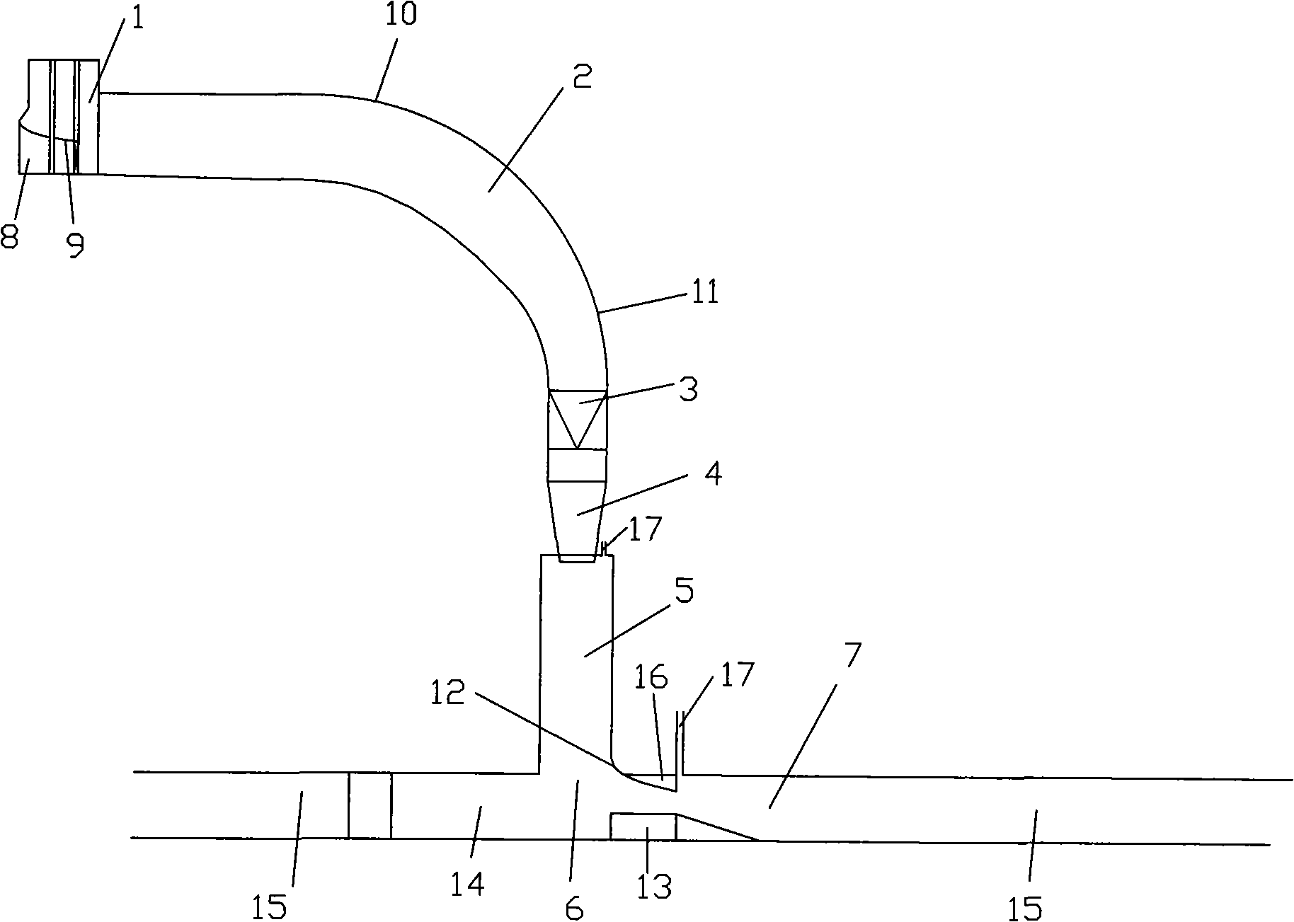
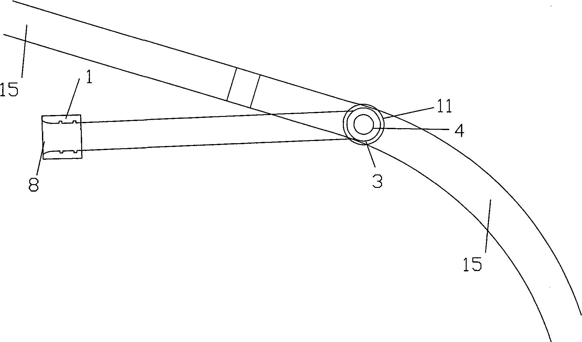
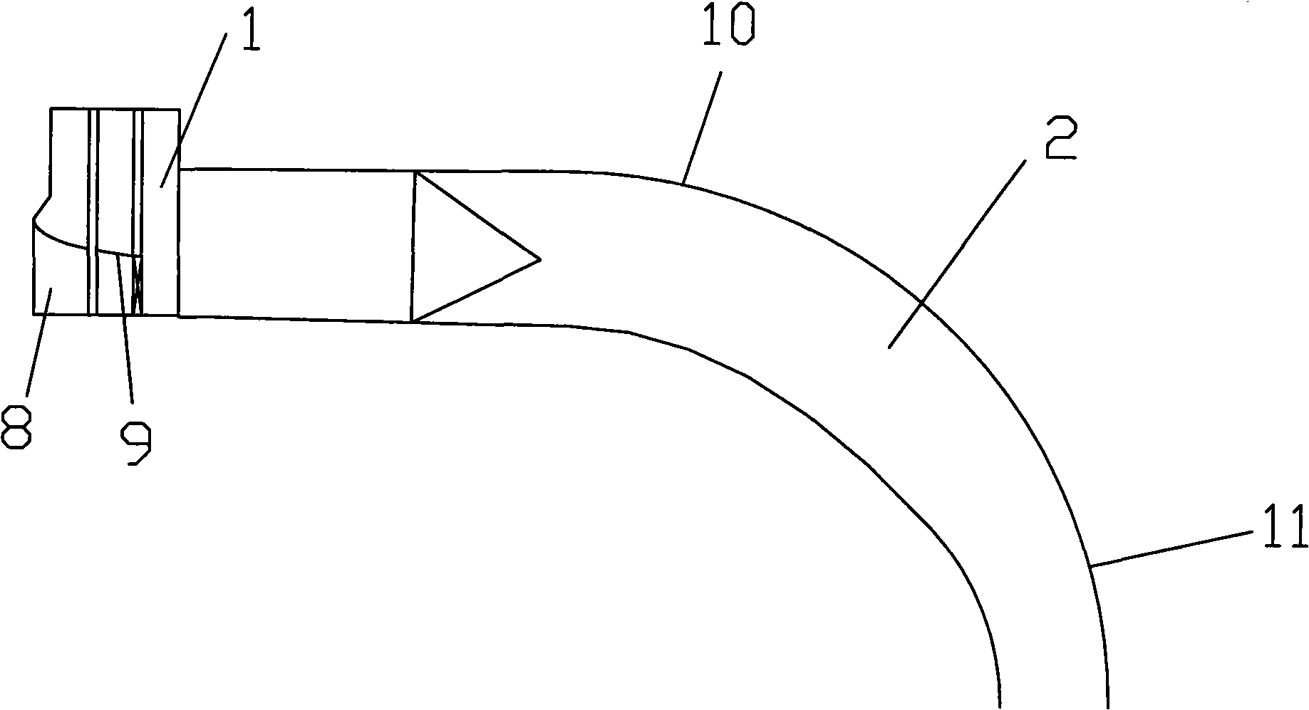
[0044] Such as figure 1 , 2 , 3, the embodiment of the present invention is to build a vertical shaft downstream of the water inlet end of the diversion tunnel. For the jet outlet, a plug is set in the first half of the diversion hole at the junction of the vertical shaft and the diversion hole to form a blind chamber.

[0045] The pressurized tunnel includes: a short pressure water inlet 1, a water diversion section 2, a water flow adjustment section 3, and a contraction section 4;

[0046] The shaft includes a shaft section 5, a shaft tunnel connection section 6, and a diversion tunnel section 7;

[0047] The short pressure water inlet 1 described therein comprises a port 8 and a pressure plate 9, the top and side curves of the port 8 are all elliptic curves, the major axis of the elliptic curve at the top is taken as the height of the orifice, and the minor axis is taken as 0.35 times the height of the orifice. The height of the orifice, the slope of the pressing plate 9...

Embodiment 2

[0065] The structure and implementation method of this embodiment are the same as in Embodiment 1, and the calculation method is as follows:

[0066] (1) Calculate the size of the short pressure inlet 1 according to the designed flood discharge flow;

[0067] Design flood flow Q 设 =2553m 3 / s, μ=0.96-0.12h / b+0.01H / h=0.913, the calculated size of short pressure water inlet 1 is h=10m, b=14m;

[0068] (2) Calculate the parabolic segment 10 coefficient according to the average velocity of the water flow;

[0069] Check the flood discharge flow as Q 校 =2741m 3 / s, calculated According to the test, the flow rate correction coefficient obtained is c=1.18, and the parabolic segment 10 coefficient a=g / (2c 2 V 2 ) = 0.0092;

[0070] (3) Calculate the outlet diameter of the shrinkage section 4 according to the flood discharge flow;

[0071] The outlet diameter of the contraction section 4 is D=α(Q 校 2 / g) 1 / 5 =1.2×(2741 2 / 9.8) 1 / 5 =18m;

[0072] (4) Determine the height...

Embodiment 3

[0075] The structure and implementation method of this embodiment are the same as in Embodiment 1, and the calculation method is as follows:

[0076] (1) Calculate the size of the short pressure inlet 1 according to the designed flood discharge flow;

[0077] Design flood flow Q 设 =2553m 3 / s, μ=0.96-0.12h / b+0.01H / h=0.913, the calculated size of short pressure water inlet 1 is h=10m, b=14m;

[0078] (2) Calculate the parabolic segment 10 coefficient according to the average velocity of the water flow;

[0079] Check the flood discharge flow as Q 校 =2741m 3 / s, calculated According to the test, the flow rate correction coefficient obtained is c=1.18, and the parabolic segment 10 coefficient a=g / (2c 2 V 2 ) = 0.0092;

[0080] (3) Calculate the outlet diameter of the shrinkage section 4 according to the flood discharge flow;

[0081] The outlet diameter of the contraction section 4 is D=α(Q 校 2 / g) 1 / 5 =1.5×(2741 2 / 9.8) 1 / 5 =22.5m;

[0082] (4) Determine the heig...


PUM


Abstract

The invention relates to a method that a diversion tunnel is rebuilt into a jet current internal energy dissipation tunnel, which belongs to the technical field of water conservancy and hydropower. The method is characterized in that: a drilled shaft is built at the downstream of the water inlet of the diversion tunnel; the lower part of the drilled shaft is connected with the top of the diversion tunnel, and the top is connected with a throat-type pressure tunnel; the outlet of the pressure tunnel in the drilled shaft is shrunk into a jet exit; a blanking adapter is arranged at the diversion tunnel of fore half section at the joint between the drilled shaft and the diversion tunnel so as to form a blind room. The method comprises the following reconstructed facilities: a short pressure water inlet, a derivation conduit section, a current adjusting section, a constriction section, a drilled shaft section, a drilled shaft tunnel connecting section and a diversion tunnel section. The method has the advantages that: the method is suitable for the reconstruction of high-head and mass flow flood discharge tunnel; a stable and effective flood discharge also can be kept in the situation of high water level at the downstream; the newly-built tunnel section occupies a small area with flexible arrangement; thereby the method can greatly reduce the cost of energy dissipating facilities.

Description

technical field [0001] The invention discloses a method for rebuilding a diversion tunnel into a jet flow internal energy dissipation vertical shaft flood discharge tunnel, which belongs to the technical field of water conservancy and hydropower. Background technique [0002] In the existing technology, converting the construction diversion tunnel into a permanent flood discharge tunnel is a relatively common construction method of hydropower station, which has high economic value and has always been an important content in the design and research of water conservancy and hydropower projects. Most of the traditional reconstructions are "dragon raising its head" and "dragon falling its tail". These two methods of reconstruction have been used for many years and have brought huge economic benefits in the construction of many hydropower projects, such as Liujiaxia and Ertan projects. With the rapid development of high dam construction, the traditional "dragon head up" and "drag...

Claims


Application Information

Patent Timeline
IPC IPC(8): E02B8/06E02B9/06
CPCY02E10/22Y02E10/20
Inventor 范子武姜树海韩昌海杨宇
Owner NANJING HYDRAULIC RES INST THE MINISTRY OF WATER RESOURCES THE MINIST
Why Eureka
Try Eureka