
Prevention and control method of water flow leapfrog in drainage structures and ladder energy dissipation work

A technology for drainage structures and energy dissipators, which is applied in construction, water conservancy engineering, marine engineering and other directions, can solve the problems of reducing the number of effective energy dissipation steps, negative effects of energy dissipation effects, abnormal pressure on the stepped surface, etc., and achieves a simple structure. Easy to operate, improve energy dissipation effect, reduce the effect of leapfrog flow

Inactive Publication Date: 2017-11-03
HOHAI UNIV +1
View PDF4 Cites 0 Cited by
  • Summary
  • Abstract
  • Description
  • Claims
  • Application Information

AI Technical Summary

Problems solved by technology

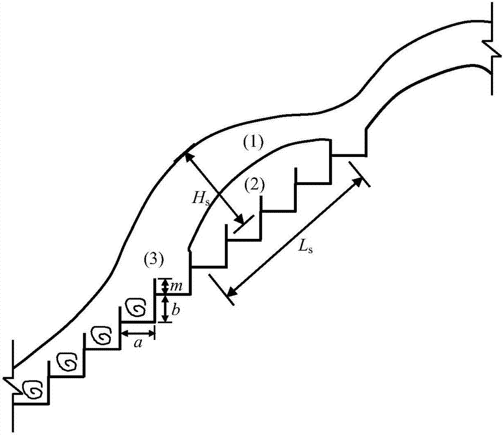
First of all, "leapfrog flow" will cause abnormal pressure on the step surface, including the negative pressure in the cavity below the leapfrog water flow and the increase of load in the impact area; secondly, it will cause the water tongue to overturn the side wall and a series of related safety problems , so it is necessary to set higher side walls in the project; finally, reduce the number of steps for effective energy dissipation, which will have a negative impact on the energy dissipation effect

Method used


Image

  • Prevention and control method of water flow leapfrog in drainage structures and ladder energy dissipation work
  • Prevention and control method of water flow leapfrog in drainage structures and ladder energy dissipation work
  • Prevention and control method of water flow leapfrog in drainage structures and ladder energy dissipation work

Examples


Embodiment 1

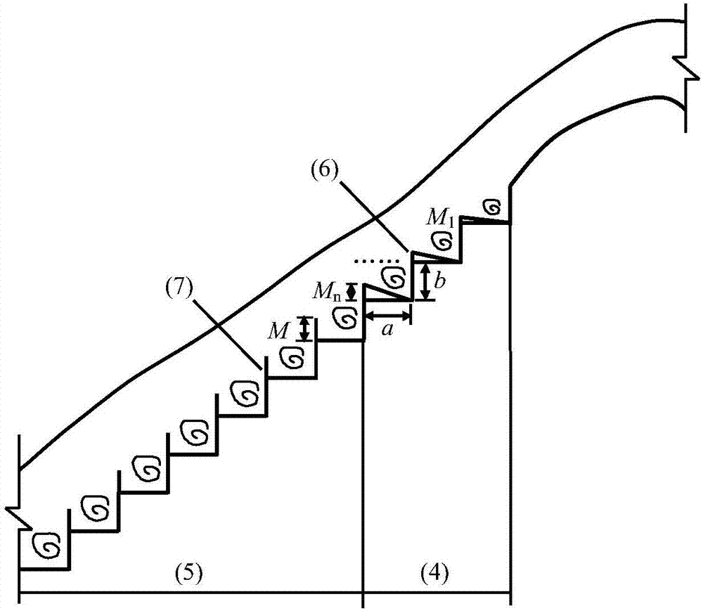
[0025] A prevention and control method for water flow leapfrogging in a drainage structure. The water flow is led to a ladder energy dissipator, and the water flow first passes through the drainage wedges 6 that are arranged on the steps of the ladder energy dissipator. The Froude number of the increasing water flow along the way matches, guides the incoming flow to form a continuous gentle wavy water flow, so that the radius of the wavy water flow gradually decreases in a smooth manner and finally connects with the water flow in the downstream energy dissipation section, ensuring that the water flow is smooth and gradual. level down.

Embodiment 2

[0027] A kind of ladder energy dissipator for the prevention and control method of water flow leapfrogging in a drainage structure, including a smooth inflow section 4 and an energy dissipation section 5, the inflow section 4 includes a section of steps, and a section of steps is provided on each step of the section of stairs There is a drainage wedge 6, and the energy dissipation section 5 includes another step connected to the first step, and tail sills 7 are provided on each step of the other step. In this embodiment, the height of the drainage wedge 6 on the step of the step increases step by step, and satisfies M 1 2 n ≤ M, M 1 , M 2 ,...,M n They are the heights of drainage wedges on the 1st, 2nd, ..., n steps of said one section of steps respectively, and M is the height of the end sill on the steps of said other section of steps; the number of steps N of energy dissipation section is greater than the steps of smooth inflow section number n. Make sure that the energ...


PUM


Abstract

The invention discloses a method for preventing water of a release structure from over-step flowing and a stepped energy dissipater. The method comprises the following steps: draining water to the stepped energy dissipater, enabling water to firstly flow through drainage wedges which are raised step by step on steps of the stepped energy dissipater, keeping the water be matched with water Froude numbers which are increased along the process, guiding the coming water to form continuous gentle wave-shaped water flow, gradually reducing the radius of the wave-shaped water flow in a smooth mode, joining downstream water at an energy dissipation section finally, and ensuring that the water flows smoothly and flows downwards step by step. The stepped energy dissipater comprises a smooth flow-in section and an energy dissipation section, wherein the flow-in section comprises a section of steps; the drainage wedges are arranged on the steps of the section of the steps; the energy dissipation section comprises another section of steps which are connected with the section of the steps; and tail ridges are arranged on the steps of the section of the steps. On the one hand, the step flow regime can be stabilized and smoothed by the drainage wedges of the smooth flow-in section, and on the other hand, an efficient energy dissipation effect can be achieved through the high tail ridges on the steps of the energy dissipation section.

Description

technical field [0001] The invention relates to a method for preventing and controlling the leapfrog flow of water in drainage structures in water conservancy and hydropower projects and a ladder energy dissipator, which is mainly used for smoothing and stabilizing the ladder flow state, avoiding the occurrence of "leapfrog flow" and improving the energy dissipation effect at the same time , to meet the needs of engineering safety. Background technique [0002] With the continuous development of water conservancy and hydropower projects, the problem of high-speed water flow in drainage structures has become increasingly prominent. Among them, the problems of energy dissipation and scour prevention and cavitation cavitation erosion have attracted special attention, and have always been difficult and restrictive problems to be solved in engineering design. Compared with the traditional energy dissipation methods of flood discharge, such as deflected flow, bottom flow, surface...

Claims


Application Information

Patent Timeline
Patent Type & Authority Patents(China)
IPC IPC(8): E02B8/06
CPCE02B8/06
Inventor 钱尚拓吴建华黄秋君吴伟伟马飞李同春
Owner HOHAI UNIV
Learn More