
Fluid operated linear motor

A linear drive, fluid technology, applied in the direction of fluid pressure actuating devices, etc., can solve the problems of large investment costs for machines and personnel, and achieve the effect of reducing weight, simplifying assembly, and reducing external dimensions.

Inactive Publication Date: 2008-10-08
FESTO AG & CO KG
View PDF5 Cites 7 Cited by
  • Summary
  • Abstract
  • Description
  • Claims
  • Application Information

AI Technical Summary

Problems solved by technology

However, since this is a completely monolithic shell, manufacturing is an extremely rigorous process and requires a large investment in manufacturing machinery and personnel

Method used


Image

  • Fluid operated linear motor
  • Fluid operated linear motor
  • Fluid operated linear motor

Examples


Embodiment Construction

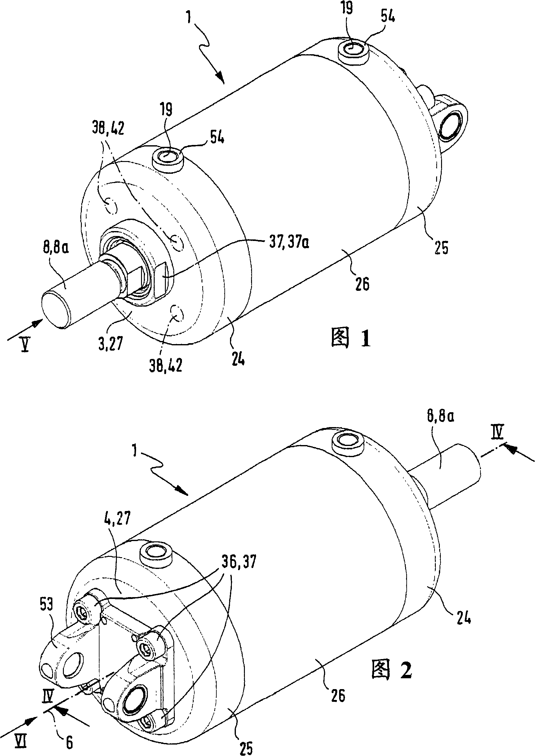
[0028] The linear actuator marked as 1 as a whole is driven by fluid power, and the driving medium may be a liquid medium or a gaseous medium. The medium is preferably compressed air.

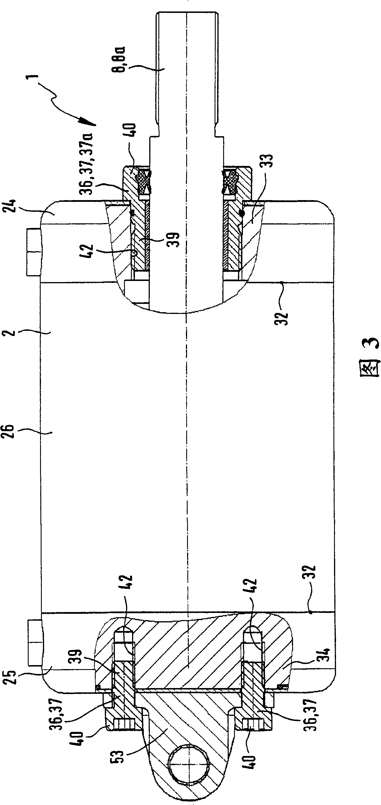
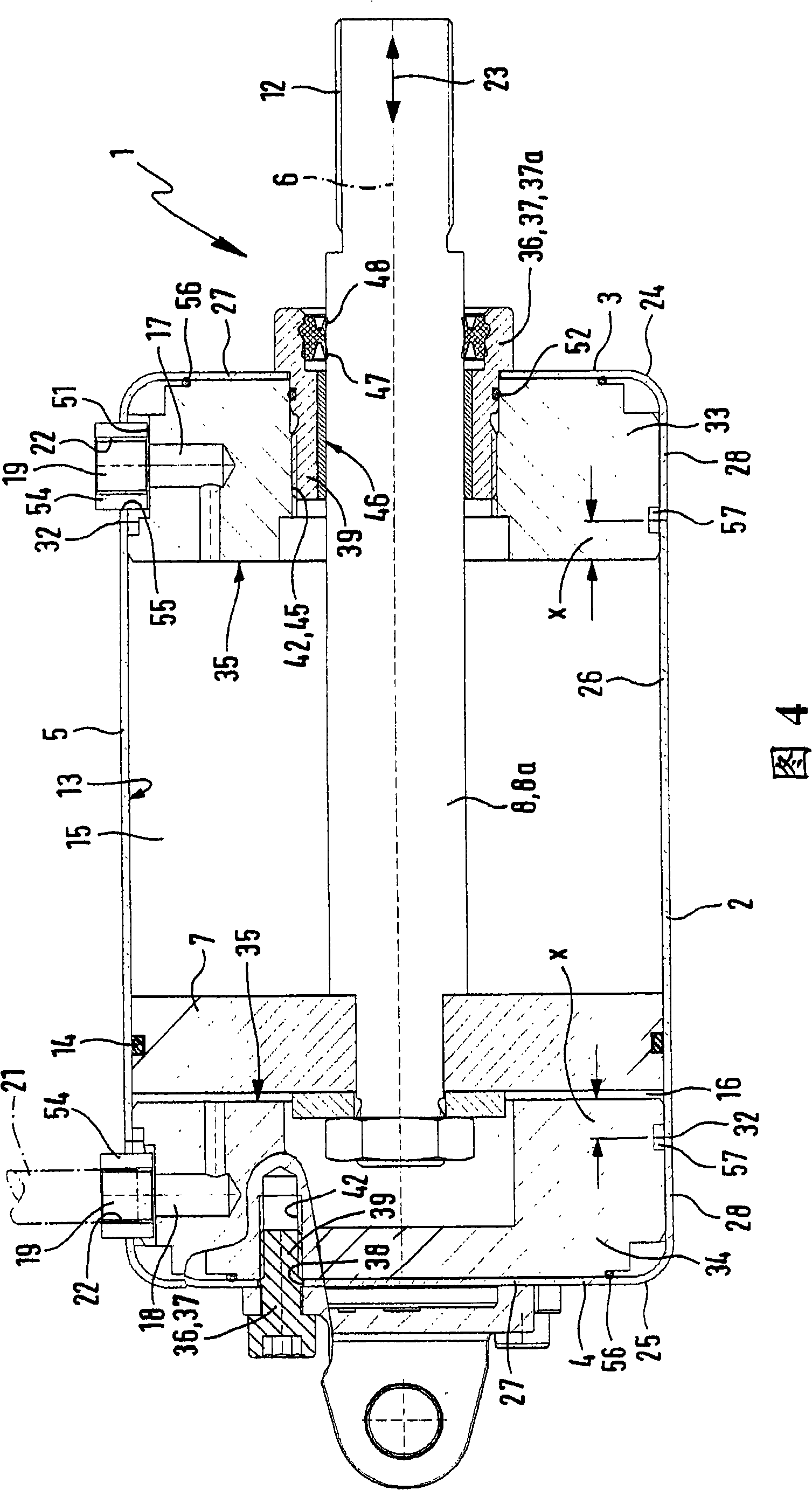
[0029] The linear actuator 1 has an elongated housing 2 having a front end connecting wall 3 and a rear end connecting wall 4, and a tubular peripheral wall 5 extending axially between them. Preferably, the housing 2 is cylindrical as a whole and particularly cylindrical.

[0030] A piston 7 is provided inside the housing, and the piston 7 slides linearly in the direction of the longitudinal axis 6 of the housing 2 and is movably coupled with a drive output portion 8 contactable from the outside of the housing 2. The output drive part 8 is preferably a piston rod 8a, which extends in the outward direction through the front end wall 3 and its part located on the outside of the housing 2 is provided with a male thread 12 or some other attachment mechanism on which The member to be displaced or positi...


PUM


Abstract

The linear drive has a housing defining a tubular peripheral wall extending between front-sided connection walls. One of the connection walls is formed by a base wall of an end cap. The cap encloses an axially immovably fixed expansion element, where the element carries an axially upstream collision surface for a piston at a front side of the connection wall. A tube section axially overlaps the element without axially supporting a radially outward piece, where the element is fixed at the housing in an area lying axially behind a front side of the element.

Description

Technical field [0001] The present invention relates to a fluid-operated linear actuator, which includes a housing for a linearly movable piston in the form of two terminal terminal walls and a tubular peripheral wall, at least one terminal wall is formed by the bottom wall of the terminal cover It is constituted that the side wall of the terminal cover defines one length of the peripheral wall and is adjacent to the tubular element that defines the other length of the peripheral wall. The terminal cover surrounds the filling body, and the filling body internally rests on the side wall and rests on it. On the bottom wall, the filling body is axially immovably fastened relative to the terminal cover, the filling body exhibits an abutment surface for the piston on its front side, and the abutment surface is located at the front of the terminal wall in the axial direction. Background technique [0002] In the case of a known fluid-operated linear actuator of this type disclosed in E...

Claims


Application Information

Patent Timeline
Patent Type & Authority Applications(China)
IPC IPC(8): F15B15/14F15B15/20
CPCF15B15/1433F15B15/24
Inventor K·斯托尔S·戈格尔R·巴克泽克
Owner FESTO AG & CO KG
Learn More