

Crystal display device and driving method thereof
A technology of liquid crystal display devices and liquid crystal capacitors, which is applied to static indicators, instruments, etc., can solve problems such as display brightness deterioration, achieve the effects of improving color deviation, better image display quality, and improving the ability to compensate for color difference
- Summary
- Abstract
- Description
- Claims
- Application Information
AI Technical Summary
Problems solved by technology
Method used
Image

Examples
no. 1 example
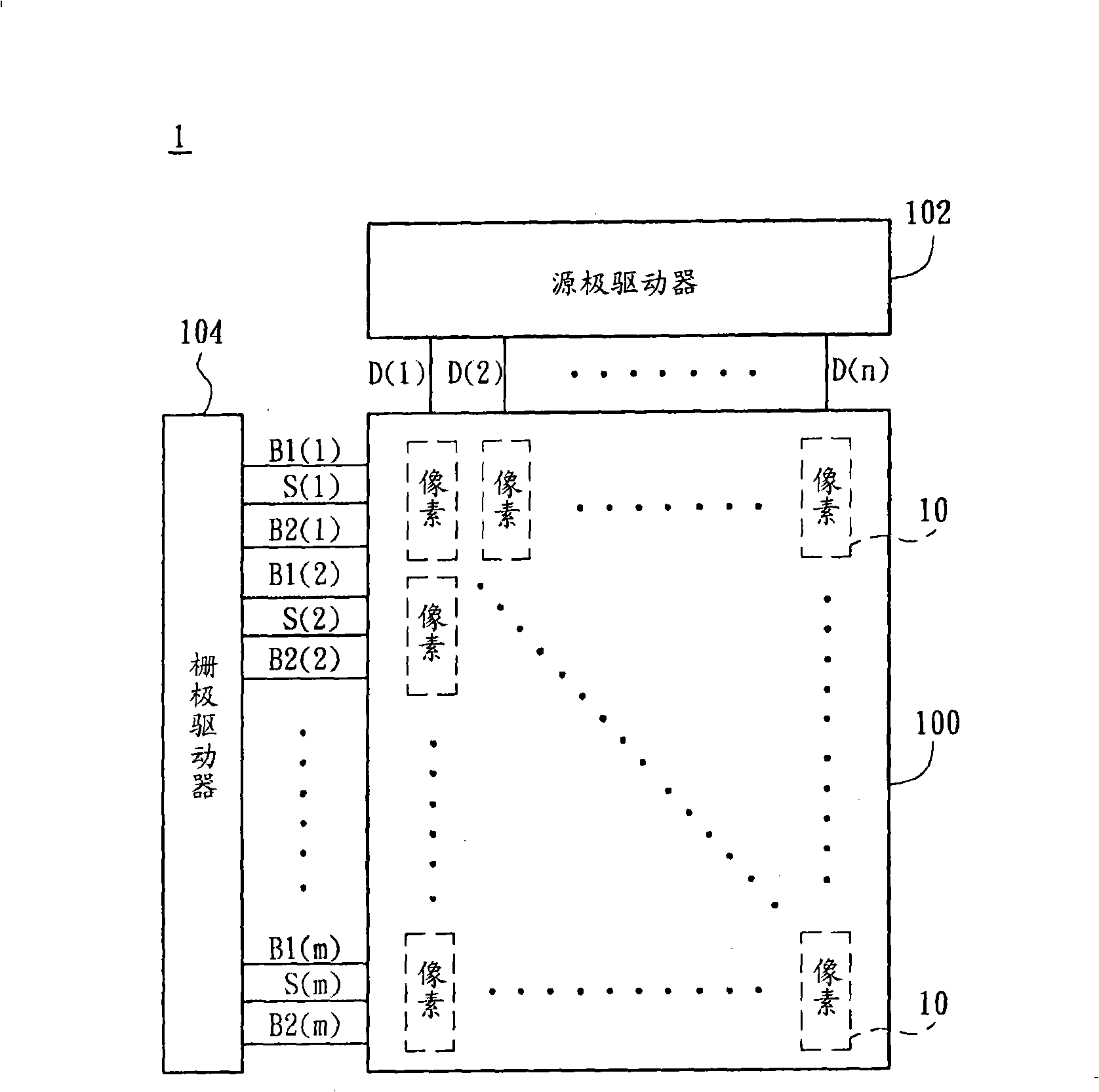
[0069] Please refer to Figure 9 , which shows a multi-view liquid crystal display device 2 according to the first embodiment of the present invention, which includes a liquid crystal panel 200 , a source driver 202 and a gate driver 204 . Wherein, the liquid crystal panel 200 includes n*m pixels 20, the source driver 202 transmits display data to a plurality of pixels 20 through the data lines D(1)˜D(n), and the gate driver 204 transmits the display data to a plurality of pixels 20 through the scan lines S(1)˜D(n). S(m) transmits the scanning signal to the liquid crystal panel 200 to turn on the pixels 20 of each row in sequence, and passes through the first storage capacitor lines B1(1)~B1(m) and the second storage capacitor lines B2(1)~B2(m) The first bias signal and the second bias signal are respectively transmitted to each pixel 20 on the liquid crystal panel 200 . Among them, the data lines D(1)~D(n) are formed on the liquid crystal panel 200 in a first direction and p...
no. 2 example
[0084] Please refer to Figure 15 As shown, it shows a multi-view liquid crystal display device 3 according to the second embodiment of the present invention. In this embodiment, each pixel 20 further includes a third sub-pixel 26, and each third sub-pixel 26 includes A liquid crystal capacitor C LC3 , a storage capacitor C ST3 and a switch assembly M 3 . In addition, in this embodiment, the storage capacitor C of the second sub-pixel 22 ST2 than liquid crystal capacitance C LC2 The ratio of is less than the storage capacitance C of the third sub-pixel 26 ST3 than liquid crystal capacitance C LC3 ratio (C ST2 / C LC2 ST3 / C LC3 ), and among the adjacent two pixels 20(j) and 20(j+1), the third subpixel 26(j) of the pixel 20(j) and the third subpixel 26(j) of the adjacent second pixel 20(j+1) Pixel 26(j+1) is misplaced. In this embodiment, among two adjacent pixels 20(j) and 20(j+1) arranged along the scanning line direction, the first sub-pixel 21(j) and the second su...
no. 3 example
[0088] Certainly, the liquid crystal display device according to the present invention can further divide the same pixel into four or more sub-pixels, and the implementation method should be realized by those skilled in the art with reference to the above-mentioned embodiments. The following will illustrate an embodiment in which the same pixel area is divided into four sub-pixels, please refer to Figure 18 As shown, it shows another liquid crystal display device 4. In this embodiment, each pixel 20 includes a first sub-pixel 21, a second sub-pixel 22, a third sub-pixel 26, and a fourth sub-pixel Pixel 27, for example, pixel 20(j) at least includes a first sub-pixel 21(j), a second sub-pixel 22(j), a third sub-pixel 26(j), and a fourth sub-pixel 27( j), the pixel 20(j+1) at least includes a first sub-pixel 21(j+1), a second sub-pixel 22(j+1), a third sub-pixel 26(j+1), and a The fourth sub-pixel 27(j+1), and so on; wherein the first sub-pixels 21(j) and 21(j+1) and the secon...
PUM
 Abstract
Description
Claims
Application Information