Continuous microwave heating apparatus

A microwave heating device and microwave technology are applied in the direction of microwave heating, which can solve the problem that the microwave heating device occupies too much space.

Active Publication Date: 2008-10-08
FOOD IND RES & DEV INST
View PDF2 Cites 27 Cited by
  • Summary
  • Abstract
  • Description
  • Claims
  • Application Information

AI Technical Summary

Problems solved by technology

For commercial continuous microwave heating devices, in addition to the heating chamber, it is necessary to install microwave leakage prevention devices at the front and rear ends of the device, so that the microwave heating device occupies too much space on the production line

Method used


Image

  • Continuous microwave heating apparatus
  • Continuous microwave heating apparatus
  • Continuous microwave heating apparatus

Examples


Embodiment Construction

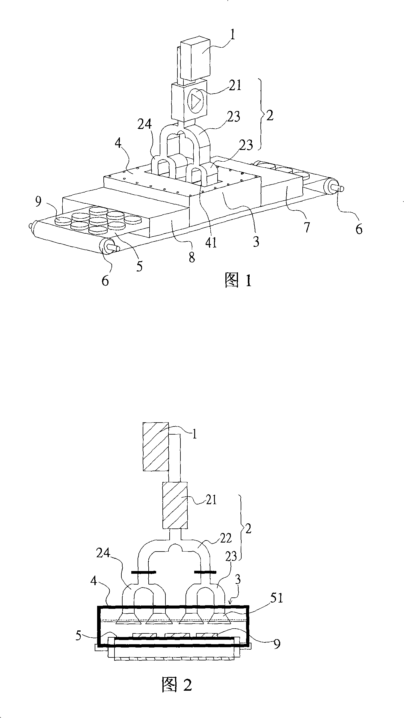
[0047] Please refer to Figure 1. Embodiment 1 of the continuous microwave heating device of the present invention includes a microwave generator 1 , a waveguide transmission part 2 and a heating cavity 3 made of metal. The microwave generator 1 is connected with the waveguide transmission part 2 to form a microwave transmitting part. The upper end of the heating cavity 3 is combined with a metal plate 4 to form a space for microwave irradiation. The inner side of the metal plate 4 at the top of the heating cavity 3 is provided with a microwave irradiation part. The metal plate 4 has a plurality of through holes 41 . The lower end of the waveguide transmission part 2 communicates with the through hole 41 and the microwave irradiation part.

[0048] The waveguide transmission part 2 includes a circulator 21 and three power dividers 22, 23, 24; the circulator 21 is used to absorb microwave reflection energy and protect the microwave emission source; the power dividers 22, 23, ...


PUM


Abstract

The present invention provides a continuous microwave heating device comprising microwave emitting part and microwave irradiating part which are connected with each other; a transmitting part is installed at lower part of the microwave irradiating part; the microwave irradiating part has a plurality of microwave irradiating unit which are configured adjacent to each other; causing the microwave of the single microwave energy from the microwave emitting part to heat the dielectric material passing through lower part of the microwave irradiating part via the movement of the transmitting part through the irradiation of the microwave irradiating unit, which is able to play the system production equipment needed by the single microwave energy and reduce the space possessed by the system and the producing cost.

Description

technical field [0001] The present invention relates to a heating device, especially a continuous heating device using microwave energy, which can rapidly heat dielectric solids and powders moving continuously in a microwave action chamber; or related to using microwaves to immediately heat porous objects, solids and powders Continuous conveying heating device for powder. Background technique [0002] Microwave energy technology is widely used in industrial heating, such as food, leather, wood, etc., and its main system development focuses on the application of electromagnetic field shapes. Since the distribution of electromagnetic field is different from that of traditional energy sources, in order to achieve uniform heating of products, the intensity of electromagnetic field needs to be distributed evenly. It is necessary to focus on the design of microwave waveguide network and microwave heating cavity. There are four kinds of electromagnetic field mode conversion or exci...

Claims


Application Information

Patent Timeline
Patent Type & Authority Applications(China)
IPC IPC(8): H05B6/78
Inventor 张俊吉黄荣丞林福文杨炳辉
Owner FOOD IND RES & DEV INST
Why Eureka
Try Eureka