Feed unit

A conveying unit, swirling technology, applied in the direction of engine components, charging systems, machines/engines, etc., can solve problems such as complex shape design

Inactive Publication Date: 2008-10-15
CONTINENTAL AUTOMOTIVE GMBH
View PDF0 Cites 0 Cited by
  • Summary
  • Abstract
  • Description
  • Claims
  • Application Information

AI Technical Summary

Problems solved by technology

The disadvantage of this pump support is the relatively complex s

Method used


Image

  • Feed unit
  • Feed unit
  • Feed unit

Examples


Embodiment Construction

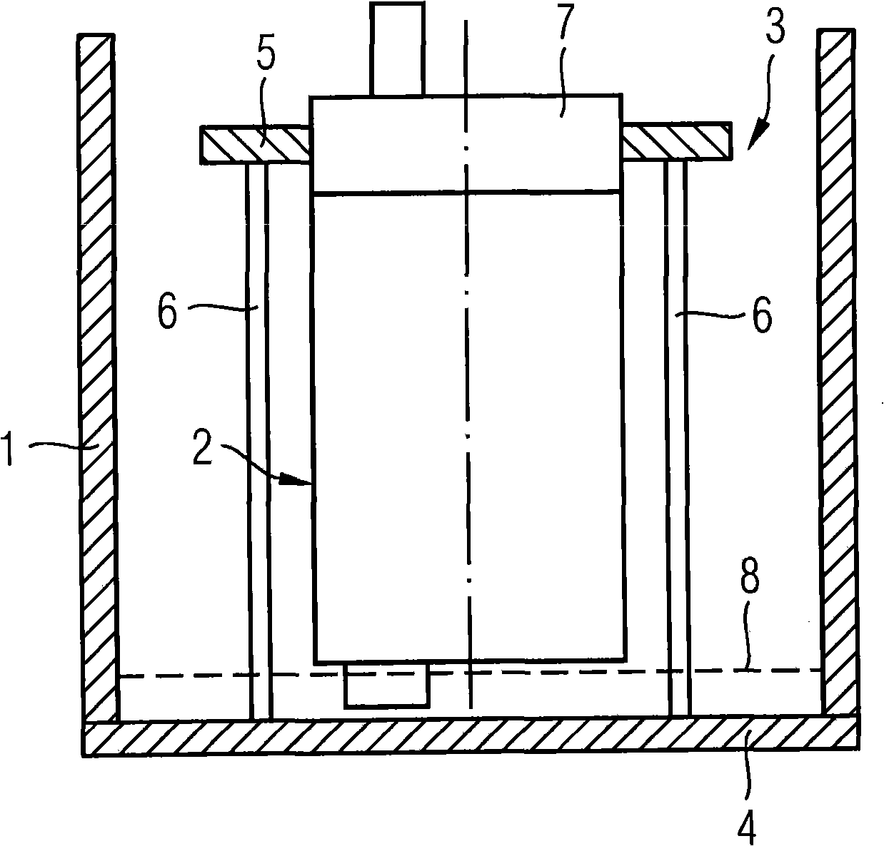
[0019] exist figure 1 The delivery unit shown in consists of a swirl box 1 in which a fuel pump 2 is arranged. The fuel pump 2 is accommodated in a pump mount 3 and is connected via this pump mount to the bottom 4 of the swirl box 1 .

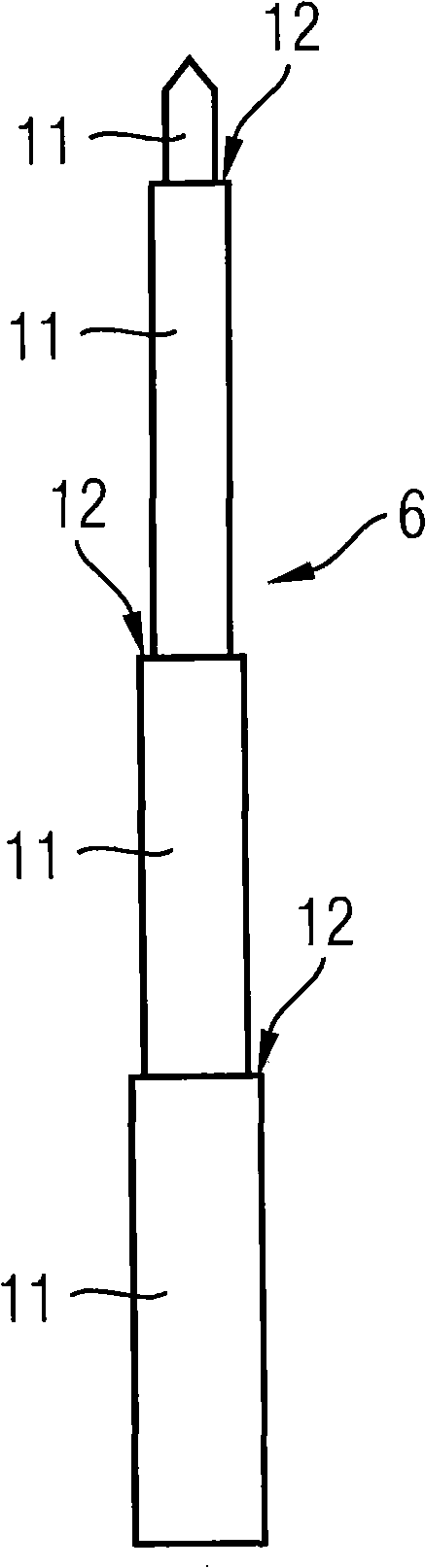
[0020] The pump support 3 consists of a mount 5 and three rods 6 . Rods 6 are pressed into recesses in bottom 4 , wherein these rods pass through pump prefilter 8 . The rods 6 extend axially parallel to the fuel pump 2 up to the level of the connecting piece 7 , where they are pressed with their ends facing away from the base 4 into recesses in the mounting 5 . The mount 5 of the pump bearing 3 is bounded with respect to its axial extent to the connecting piece 7 of the fuel pump 2 .

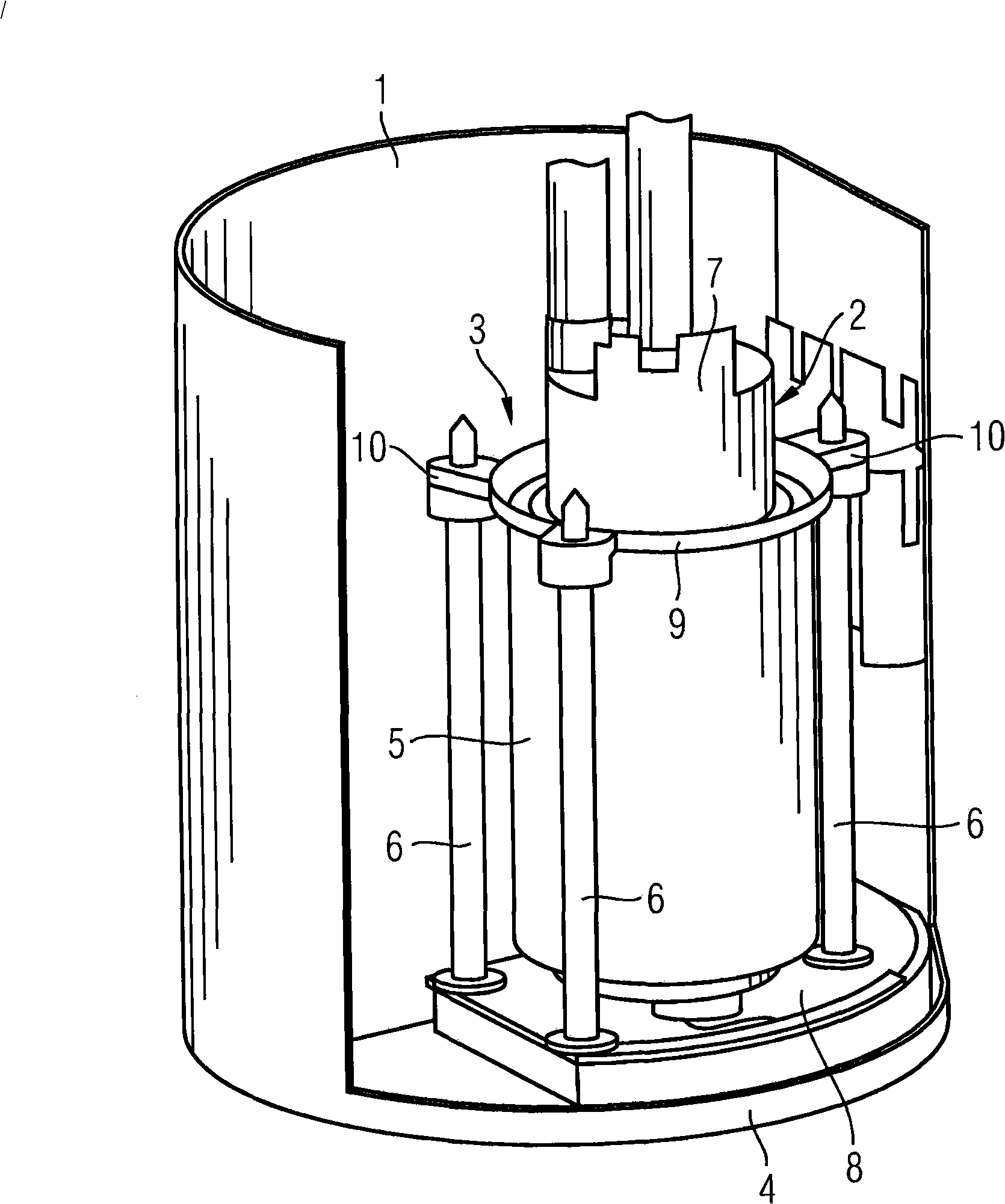
[0021] exist figure 2 , a fuel pump 2 is arranged in the swirl box 1 shown in section. The fuel pump 2 is accommodated in a mount 5 of the pump carrier 3 , the mount 5 being pot-shaped so that it accommodates almost the entire fuel pump 2 . The upper end 9...


PUM


Abstract

The invention relates to a feed unit having a surge chamber 1, a fuel pump 2, which is arranged in the surge chamber 1, and a pump holder 3, the fuel pump 2 being arranged in the pump holder 3 and the pump holder 3 being fastened in the surge chamber 1. The pump holder 3 has at least two rods 6 which are fastened in the surge chamber 1, the rods 6 being connected to a mount 5 for the fuel pump 2.

Description

technical field [0001] The invention relates to a delivery unit with a swirl box, a fuel pump arranged in the swirl box and a pump support, wherein the fuel pump is arranged in the pump support and the pump support is fastened to the swirl box middle. Such delivery units are used to deliver fuel from a fuel tank of a motor vehicle to an internal combustion engine of the motor vehicle. Background technique [0002] Delivery units of the type mentioned at the outset have been known for a long time in the prior art. In this case, the pump mount of the delivery unit serves on the one hand to accommodate the fuel pump in a fixed position in the swirl box, and on the other hand the pump mount has the task of damping vibrations generated by the fuel pump or damping them Transfer to swirl box. Undesirable noise can be reduced in this way. In particular to reduce vibrations of fuel pumps a number of pump mounts are known having a first mount for mounting the fuel pump and a secon...

Claims


Application Information

Patent Timeline
IPC IPC(8): F02M37/10
CPCF02M37/106F02M37/103
Inventor 卡尔·埃克迪特尔·哈吉斯特马蒂亚斯·卡德莱尔马丁·马斯奥利弗·舍纳特米夏埃尔·泰歇特
Owner CONTINENTAL AUTOMOTIVE GMBH
Why Eureka
Try Eureka