
Paper punch with centering device

A technology of punching device and positioning device, which is applied in file folders, printing, metal processing, etc. It can solve the problems of poor punching ability and inability to adapt to different sizes of paper, and achieve good reliability, Achieve simple, easy-to-use effects

Active Publication Date: 2008-10-22
MFG DARTICLES DE PRECISION & DE DRESSIN - M A P E D
View PDF2 Cites 3 Cited by
  • Summary
  • Abstract
  • Description
  • Claims
  • Application Information

AI Technical Summary

Problems solved by technology

Aside from its poor punching ability, this hole punch doesn't work well with different sized papers, at least in its original embodiment

Method used


Image

  • Paper punch with centering device
  • Paper punch with centering device
  • Paper punch with centering device

Examples


Embodiment Construction

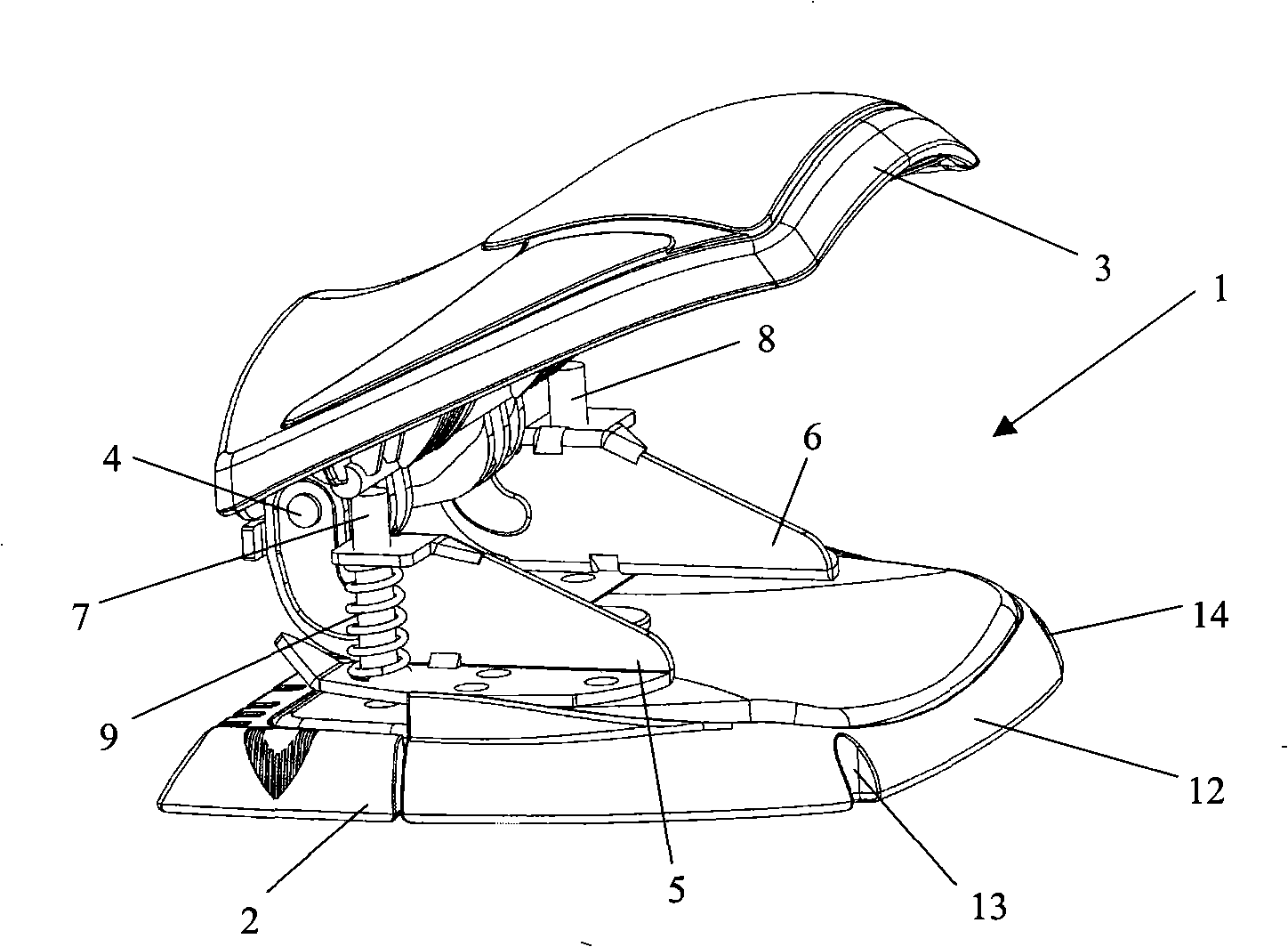
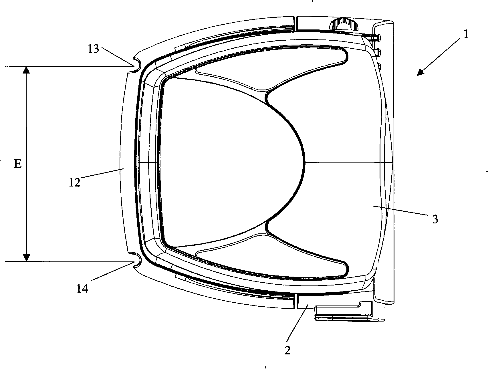
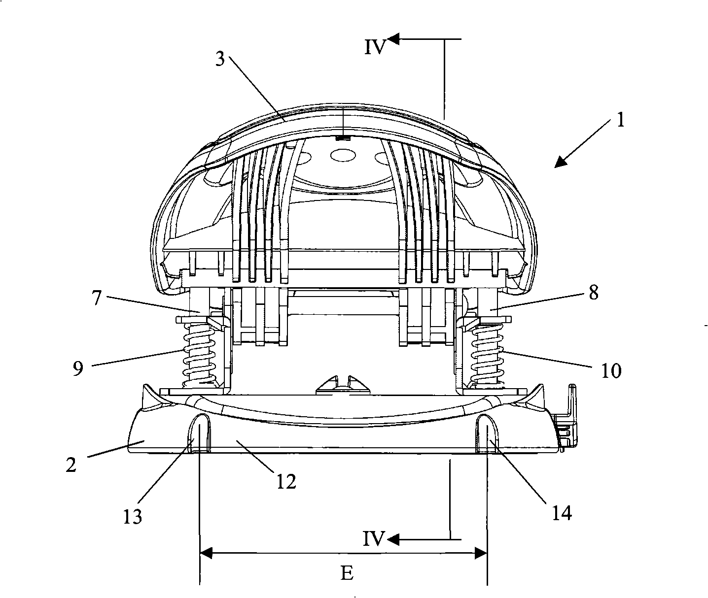
[0035] Figure 1 to Figure 4 A paper hole punch is shown, which is designated as a whole by reference numeral 1 and which is designed in one embodiment to simultaneously punch two holes at a distance E of, for example, 80 mm.

[0036] In known manner, the hole punch 1 comprises a base 2 and a tray-shaped handle 3 which is pivotally mounted about a transverse axis 4 on side supports 5 and 6 which are fixed to the base 2 on the upper face. The handle 3 cooperates with two punches 7 and 8, the punches 7 and 8 are installed so as to slide parallel to each other, and rebound upwards under the action of the corresponding springs 9 and 10, the distance between the punches 7 and 8 is E Corresponds to the desired hole spacing.

[0037] On the "front" side substantially perpendicular to the axis of rotation 4 of the handle 3, the two side supports 5 and 6 each have a slot 11 into which the edges of one or more sheets of paper to be perforated can be inserted.

[0038] On the opposite...


PUM


Abstract

The punch (1) has two piercers movably mounted relative to a base (2), a pallet shaped activation lever (3) for simultaneously displacing the piercers relative to the base. Symmetrical notches (13, 14) are provided at a longitudinal rear edge (12) of the base for positioning the base relative to rings (16, 17) of a binder (15) such that the base is applied through exterior in a predetermined position against the rings. A center distance of the rings corresponds to a predetermined center distance (E) of the piercers.

Description

technical field [0001] The invention generally relates to the technical field of stationery and office supplies. In particular, the invention relates to a paper punch designed for punching paper for introduction into folders with rings. The present invention further relates to a paper hole punch with a centering device that allows precise positioning of one or more sheets of paper to be punched relative to the hole punch itself so that the holes are positioned precisely when punching. position and / or have precise spacing. Background technique [0002] In order to achieve a good visual effect on file folders with rings, all added paper must be perforated correctly so that it fits with other papers previously placed in the ring. [0003] In European patent application EP 1332845A2, a conventional paper hole punch is shown in the preamble of claim 1 thereof. This hole punch is equipped with optics that control the good insertion of the paper to be punched. However, this opt...

Claims


Application Information

Patent Timeline
Patent Type & Authority Applications(China)
IPC IPC(8): B26F1/36B26D7/01B42F13/40
CPCB26D7/015B26D2007/0087B26D7/2628B42F13/404B26F1/36
Inventor 丹尼尔·拉卡迈尔伯鲁诺·格斯泰尔德
Owner MFG DARTICLES DE PRECISION & DE DRESSIN - M A P E D
Learn More