Bottom lifting type arrester
A technology for car barriers and mine cars, which is applied in the direction of forced railway car stops, railway car body parts, transportation and packaging, etc. The effect of working dead zone, solving serious defects, and increasing the protection range of sports cars
- Summary
- Abstract
- Description
- Claims
- Application Information
AI Technical Summary
Problems solved by technology
Method used
Image
Examples
Embodiment 1
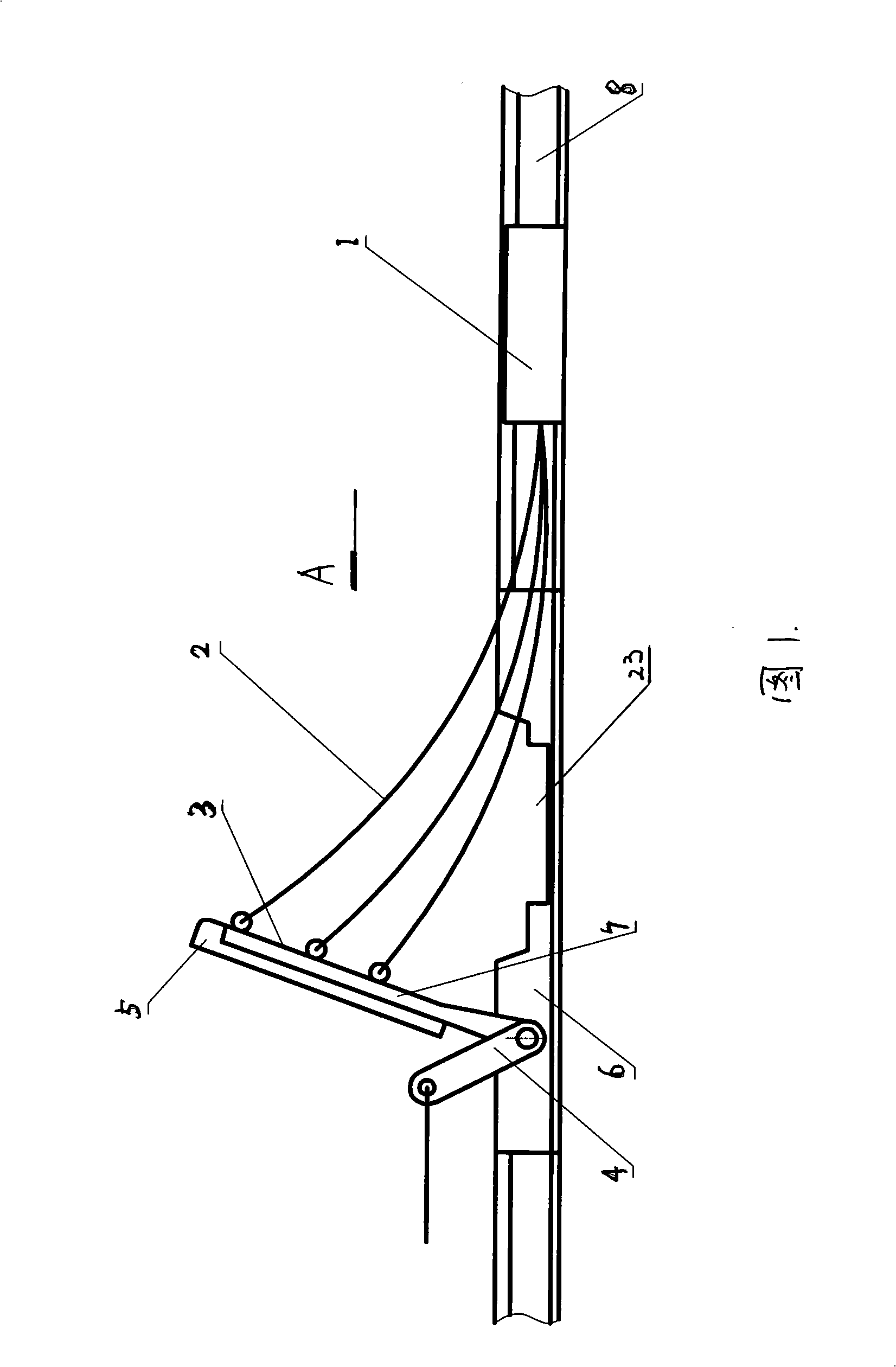
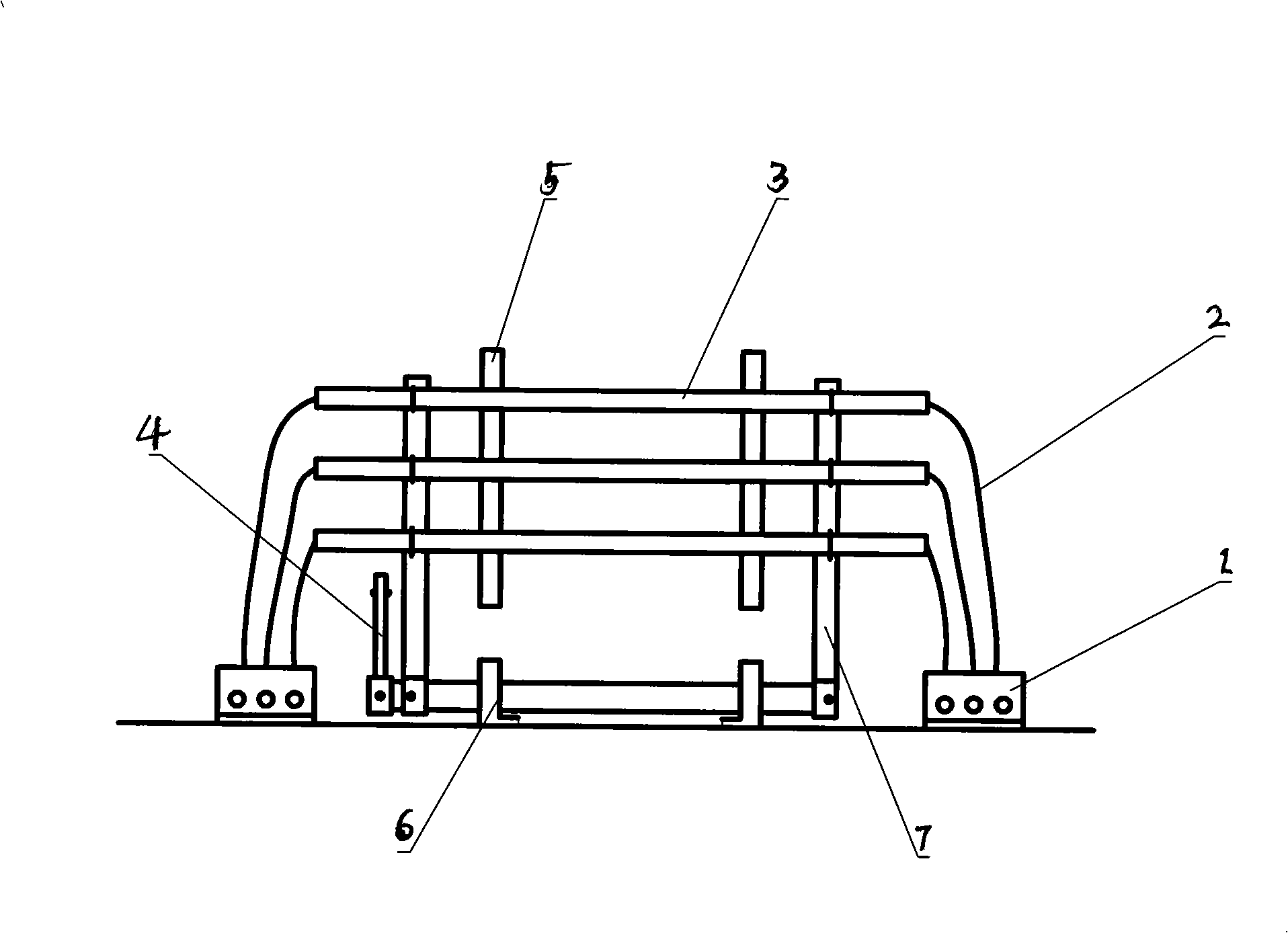
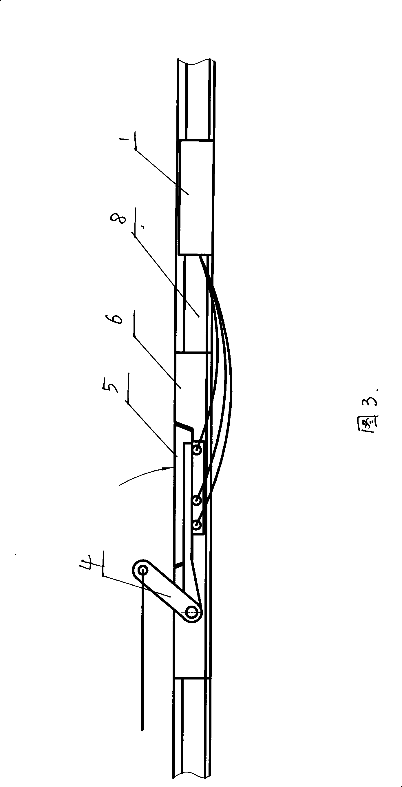
[0026] The present embodiment is accomplished in this way, a bottom lift type car barrier is composed of a buffer 1, a steel wire rope 2, a net 3, a lifting mechanism 4, a track bridge 5, a base 6, a net stick connection support 7, and a track 8 ( See accompanying drawing 1, 2).
[0027] Wire rope 2 passes through retaining net 3 two ends and is respectively connected to buffer 1 on both sides of track, retaining net 3 is connected with lifting mechanism 4, track bridge 5 is above base 6, and base 6 is connected with track 8. The lifting mechanism 4 can open or close the screen. When the retaining net was in the closed state, the rail bridge 5 was attached to the base 6, and the retaining net was in the net retaining chamber 23 below the rail bridge 5, and the hoisting mine car passed through the rail bridge 5. Track bridge 5 is opened when opening, and hoisting mechanism 4 opens screen 3 . When the mine car sports car, the head car hits the net 3, so that the net 3 is disen...
Embodiment 2
[0031] In this embodiment, the connection support is integrated with the track bridge. Rail bridge 5 plays the effect of net stick connection support 7 again, and cylinder 9 promotes retaining net 3 to rotate around rotating shaft 11 through power arm 10, and rail bridge 5 is connected with rotating shaft 11 by the shear pin that can be cut off. When the runaway mine car bumped into the barrier, the net 3 would disengage from the track bridge 5, and the track bridge 5 would fall down under the impact of external force to cut off the shear pins that it was connected with the rotating shaft 11, so as to prevent the track bridge 5 from being damaged.
Embodiment 3
[0033] In this embodiment, the mesh sticks are connected by soft link chains. When the retaining net falls, it can be folded in the retaining net storage chamber 23. Block net 3 is fixed on tackle 19 by screw or iron wire and is pulled by traction rope, and column 18 leads tackle 19, and pulley 17 changes traction direction. The track bridge 5 is connected with the shaft 16 , and the finger 13 and the balance arm 14 are connected with the shaft 16 . The balance arm 14 and the spring 15 are used to adjust the balance state, so that the track bridge will not fall naturally.
[0034] Working principle: when the block net 3 is opened, the tackle moves up, the driving rod 12 fixed on the tackle leaves the finger 13, the track bridge 5 is opened and maintained under the action of the balance force, and the block net is in an open state. When the retaining net 3 is closed, the tackle moves down, and the retaining net 3 is folded in the retaining net storage room 23 below the track ...
PUM
 Abstract
Description
Claims
Application Information
 - R&D
- Intellectual Property
- Life Sciences
- Materials
- Tech Scout
- Unparalleled Data Quality
- Higher Quality Content
- 60% Fewer Hallucinations
Browse by: Latest US Patents, China's latest patents, Technical Efficacy Thesaurus, Application Domain, Technology Topic, Popular Technical Reports.
© 2025 PatSnap. All rights reserved.Legal|Privacy policy|Modern Slavery Act Transparency Statement|Sitemap|About US| Contact US: help@patsnap.com


