

Line focusing solar vacuum heat-collecting tube sealing structure and unloading device
A technology of vacuum heat collector tube and unloading device, which is applied in the direction of solar thermal device, solar collector, solar collector safety, etc., can solve problems such as gaps
- Summary
- Abstract
- Description
- Claims
- Application Information
AI Technical Summary
Problems solved by technology
Method used
Image


Examples
Embodiment 1
[0028] Embodiment 1: direct fusion sealing method
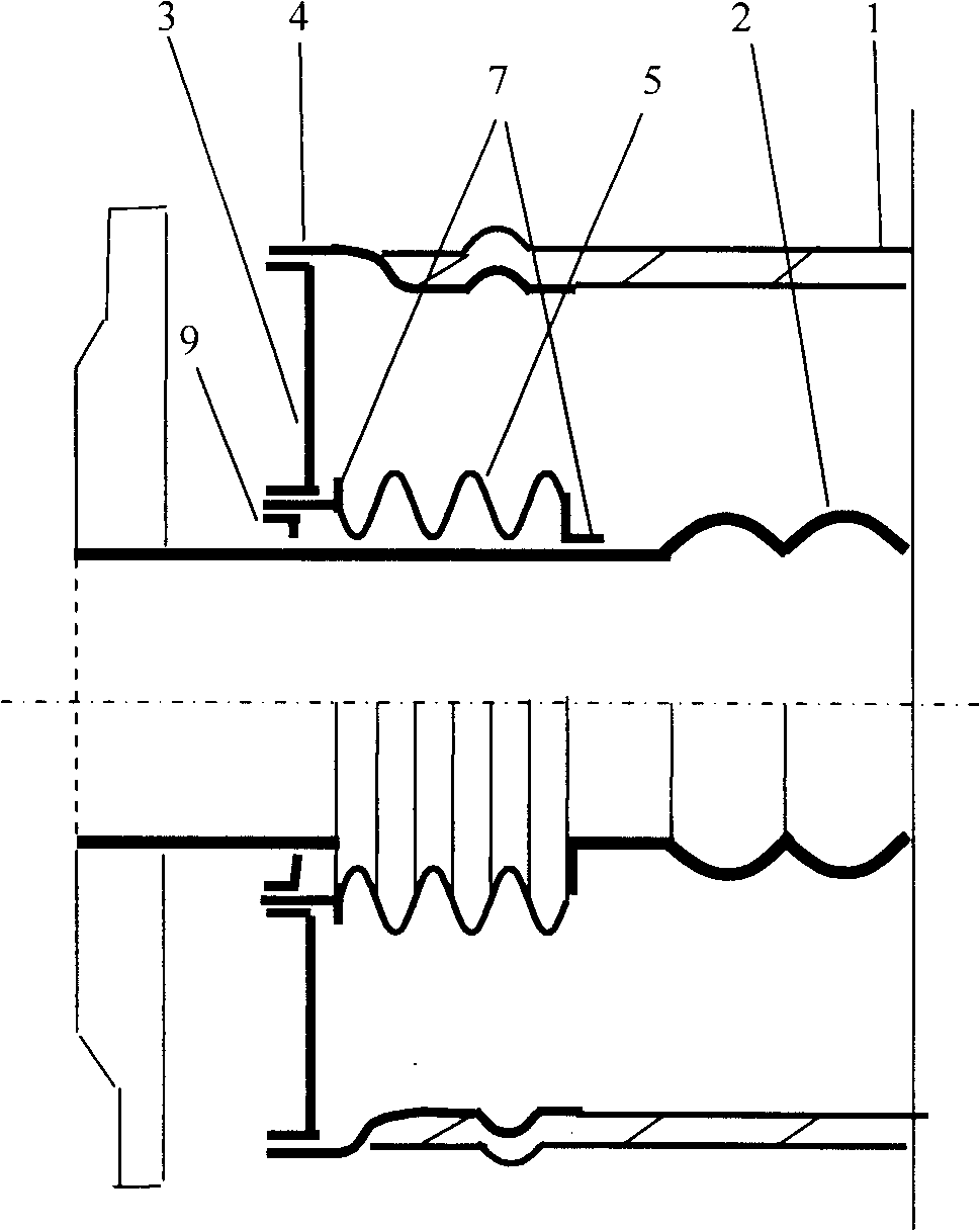
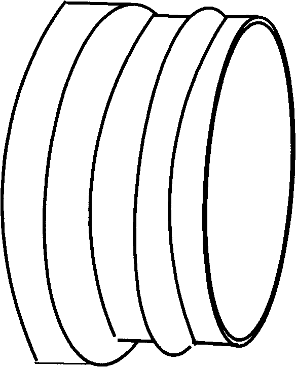
[0029] Select iron-nickel kovar alloy and glass outer tube with the same linear expansion coefficient. Firstly, the iron-nickel kovar alloy part 4 is stamped and formed into a spherical head or a tubular part with grooves. After atomization treatment, it is placed on a fixture or In the mold cavity, the end of the glass outer tube 1 is set on the exposed spherical tubular part of the Kovar alloy part 4, and the glass is melted with flame on a glass lathe or a rotary workbench, or the method of static sealing in the mold cavity can also be adopted , after the iron-nickel kovar alloy 4 and the glass outer tube 1 are fully welded, heat treatment according to the glass operation regulations, annealing and stress relief, and then used as a component for standby. The metal end cover 3 is stamped and made into a central concave-shaped opening end cover, the two ends of the unloading device bellows 4 are welded with pipe joints 7, th...
Embodiment 2
[0030] Embodiment 2: Indirect fusion sealing method
[0031] Select iron-nickel kovar alloy 4 with the same linear expansion coefficient, low-melting glass-ceramic sealing material 6 and glass outer tube 1, and iron-nickel kovar alloy part 4 is stamped and made into different convex ring parts in the inner circle, and the outer glass tube 1 The end is processed into a glass flange of the same shape slightly larger than the iron-nickel Kovar alloy part 4, and the low-melting glass-ceramic sealing material 6 is evenly coated on the atomized iron-nickel Kovar alloy part 4 and glass On the sealing surface of the outer tube 1, the opening is placed upwards in a high-temperature furnace for welding, and after full welding, it is heat treated according to the glass operation regulations, annealed and stress-relieved, and then used as a component for standby use. The metal end cover 3 is stamped and made into a central concave-shaped opening end cover, the two ends of the unloading de...
Embodiment 3
[0033] Using the inner glass flange processing method, first cut the glass outer tube 1, process the inner sealing surface of the bell mouth flange with the opening inward at the end of the glass outer tube 1, and process the iron-nickel kovar alloy part 4 into an enlarged end of the same shape. For the tubular piece with a bell mouth, glass sealing materials 6 are respectively placed between the atomized iron-nickel kovar alloy piece 4 and the contact surface of the glass flange, and are welded in a static high-temperature environment. Since the iron-nickel kovar alloy part 4 is installed in the flange of the glass outer tube 1, it can bear greater axial stress from the thermal expansion of the metal inner tube, which is more conducive to stabilizing the unloading structure. Others are the same as before. Such as Figure 9 shown.
PUM
 Abstract
Description
Claims
Application Information