

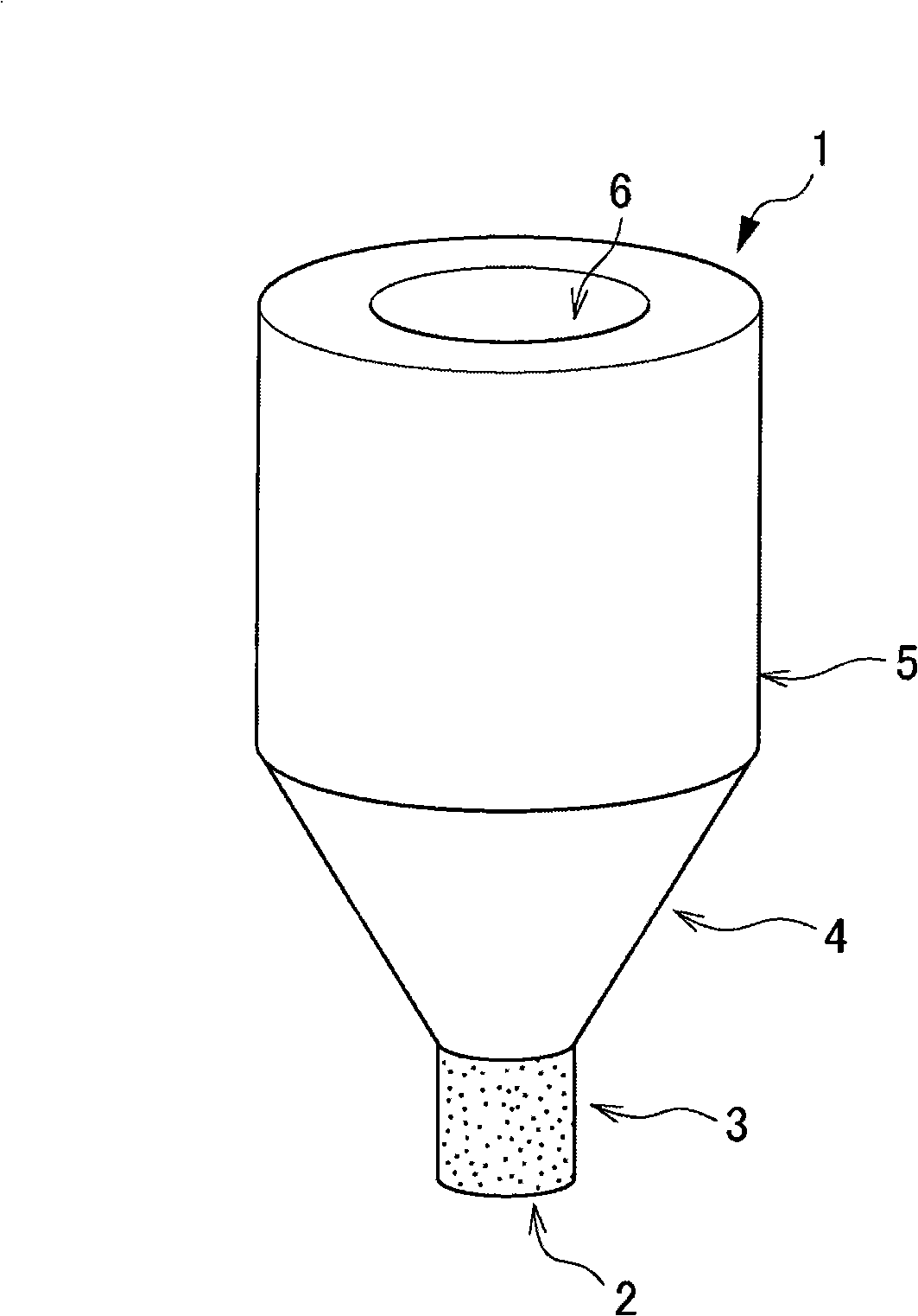
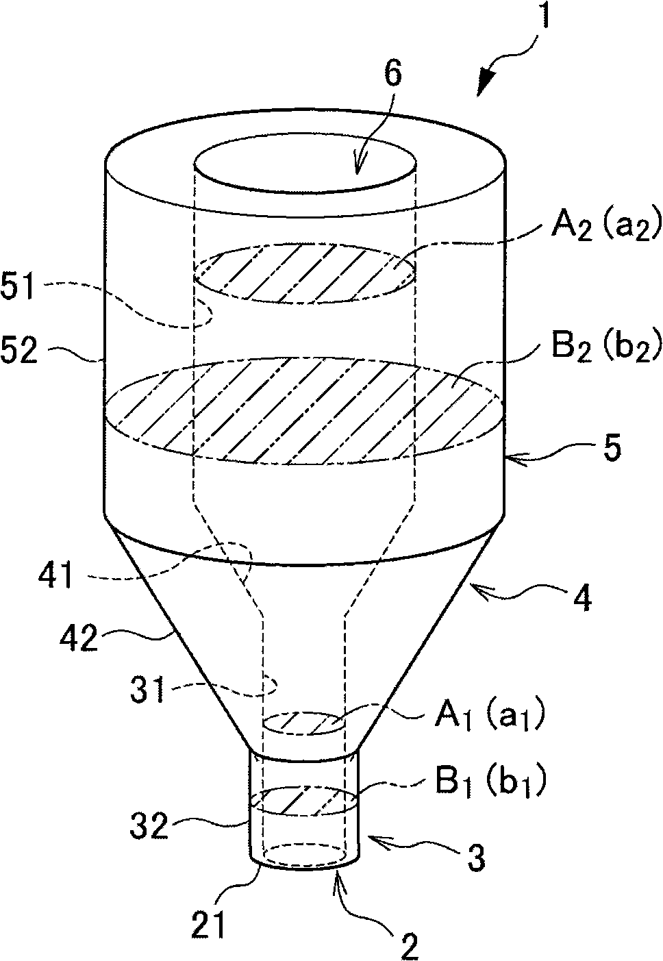
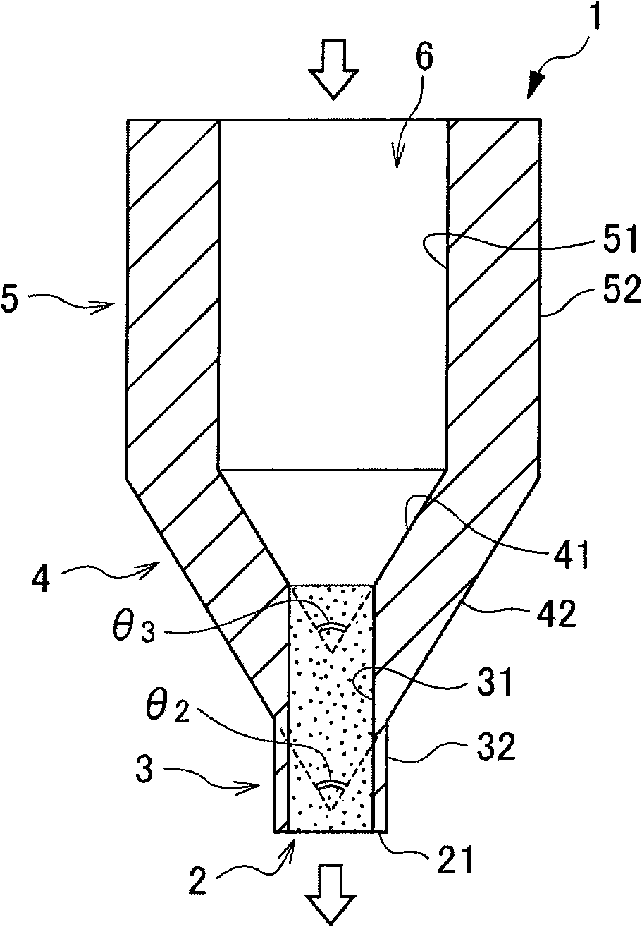
Melt material outlet nozzle
A technology of melt and nozzle, applied in the direction of feeder nozzle, liquid is divided into bead droplets, etc., can solve the problems of poor glass body and inability to flow out glass flow, etc.
- Summary
- Abstract
- Description
- Claims
- Application Information
AI Technical Summary
Problems solved by technology
Method used
Image

Examples
Embodiment
[0100] Hereinafter, examples of the present invention will be described, but the scope of the present invention is not limited to the following examples.
[0101]
[0102] A nozzle for producing tiny spherical particles with a diameter of 1 mm was fabricated. A cylindrical material formed of platinum was prepared, and a through hole with a diameter of 0.8 mm was drilled in the center of the material using a tool obtained by modifying a commercially available turning tool or drill. Then, a wire rod having a diameter of 0.5 mm was produced, and the surface inside the through-hole was subjected to wire grinding processing using an abrasive of the wire rod and diamond. And, the end and the outer surface of this material are cut into a predetermined shape, and the inner surface, the outer surface, and the end surface have a centerline average roughness (Ra) of 0.2 μm by grinding using a polishing cloth or a whetstone. The melt flows out of the nozzle. Here, using standard sampl...
PUM
 Abstract
Description
Claims
Application Information