

Vertically-arranged impact screen
A technology of impact sieve and vertical placement, which is applied in the direction of filter sieve, solid separation, grille, etc., which can solve the problems of insufficient screening effect of viscous materials, and achieve the effect of highlighting substantive characteristics and obvious screening effect
Inactive Publication Date: 2008-10-29
孙功民
View PDF1 Cites 2 Cited by
- Summary
- Abstract
- Description
- Claims
- Application Information
AI Technical Summary
Problems solved by technology
In the prior art, the well-known technology is patent No. 200420097464.0, which was applied by the applicant and authorized by the State Intellectual Property Office. Arranged staggered up and down to save the area occupied by screening. This structure can indeed achieve the same screening effect while saving the occupied area, but the effect on screening viscous materials is extremely insufficient. the shortcomings of the existing technology
Method used
View moreImage
Smart ImageViewing Examples

Examples
Embodiment Construction
Login to View More PUM
 Abstract
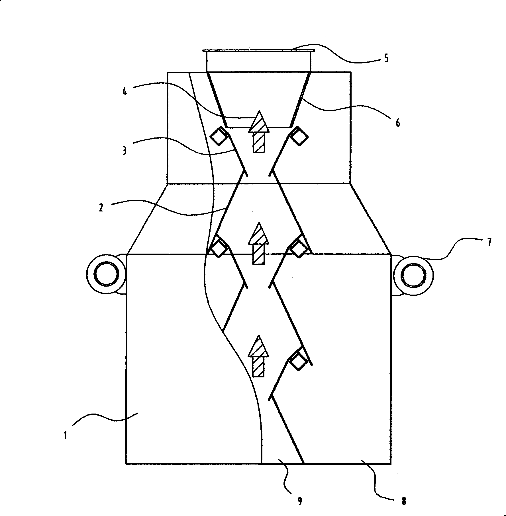
The invention provides an industrial screen, in particular to a technical proposal of an erect impact screen; the technical proposal includes a feeding port and a box including a discharge hole of plus mesh and a discharge hole of undersieves, and sieve plates are arranged in the box; the proposal is that: at least two impact screen separation units are vertically arranged in the box in an up and down way; the impact screen separation units are provided with distributors, the tops of the cross sections of which take a conical shape, at the position of the central lateral plane of the box from top to bottom, two sieve plates, which are symmetrical by taking the central lateral plane of the box as an axle, are arranged at the two sides of the middle lower part in a V-shaped way, and two guide boards of the material under the screen, which are symmetrical by taking the central lateral plane of the box as an axle, are arranged at the lower parts of the two sieve plates in an inverted V-shaped way. The discharge hole of the plus mesh is the space between the impact screen separation units and the two guide boards of the material under the screen, and the discharge hole of the undersieves is the space between the two guide boards of the material under the screen and the side wall of the box.
Description
A vertical impact screen Technical field: The invention relates to an industrial sieve used in industry to sieve materials, in particular to a vertical impact sieve. Background technique: In the prior art, the well-known technology is patent No. 200420097464.0, which was applied by the applicant and authorized by the State Intellectual Property Office. Arranged staggered up and down to save the area occupied by screening. This structure can indeed achieve the same screening effect while saving the occupied area, but the effect on screening viscous materials is extremely insufficient. It is the weak point that existing technology exists. Invention content: The purpose of the present invention is to provide a vertical impact screen technical solution for the deficiencies in the prior art. The potential energy of the feeder separates the materials and impacts the sieve plates on both sides for screening, which is extremely beneficial for screening viscous materials. Th...
Claims
Login to View More Application Information
Patent Timeline
 IPC IPC(8): B07B1/28B07B1/46
Inventor孙功民孟祥义马秀娟
Owner孙功民