
Screening machine with large screening area

A screening machine and screening technology, applied in the direction of filter screen, solid separation, grille, etc., can solve the problems of screen shaft damage, screen non-abrasion, wear, etc., so as to increase the screen area and reduce material blockage. , Strengthen the effect of screening speed

Pending Publication Date: 2018-10-12
四川皇龙智能破碎技术股份有限公司
View PDF0 Cites 1 Cited by
  • Summary
  • Abstract
  • Description
  • Claims
  • Application Information

AI Technical Summary

Problems solved by technology

[0003] Existing sieving machine products are mainly screened through multiple sieve holes on the sieve, but the traditional sieve is not wear-resistant, and will undergo serious wear and tear after long-term use, and needs to be replaced in time, and the traditional sieve The screen is prone to clogging. In order to reduce the probability of clogging as much as possible, most screening machines use vibrating screens, but the screens are still not wear-resistant, have a lot of noise, and cannot achieve a good screening effect. low efficiency
There is already a screening machine that uses multiple hollow screening shafts to increase the screening area. The side wall of the screening cylinder is made of multiple steel bars, and gaps are formed between the steel bars for the passage of fine materials, but the shape is Long strips of material will still be mixed with fine materials through the high screening shaft, and the material is easy to get stuck between the two screening shafts, affecting the screening effect and even causing damage to the screening shaft

Method used


Image

  • Screening machine with large screening area
  • Screening machine with large screening area
  • Screening machine with large screening area

Examples


Embodiment Construction

[0025] In order to make the purpose, technical solution and advantages of the present invention clearer, the present invention will be further elaborated below in conjunction with the accompanying drawings.

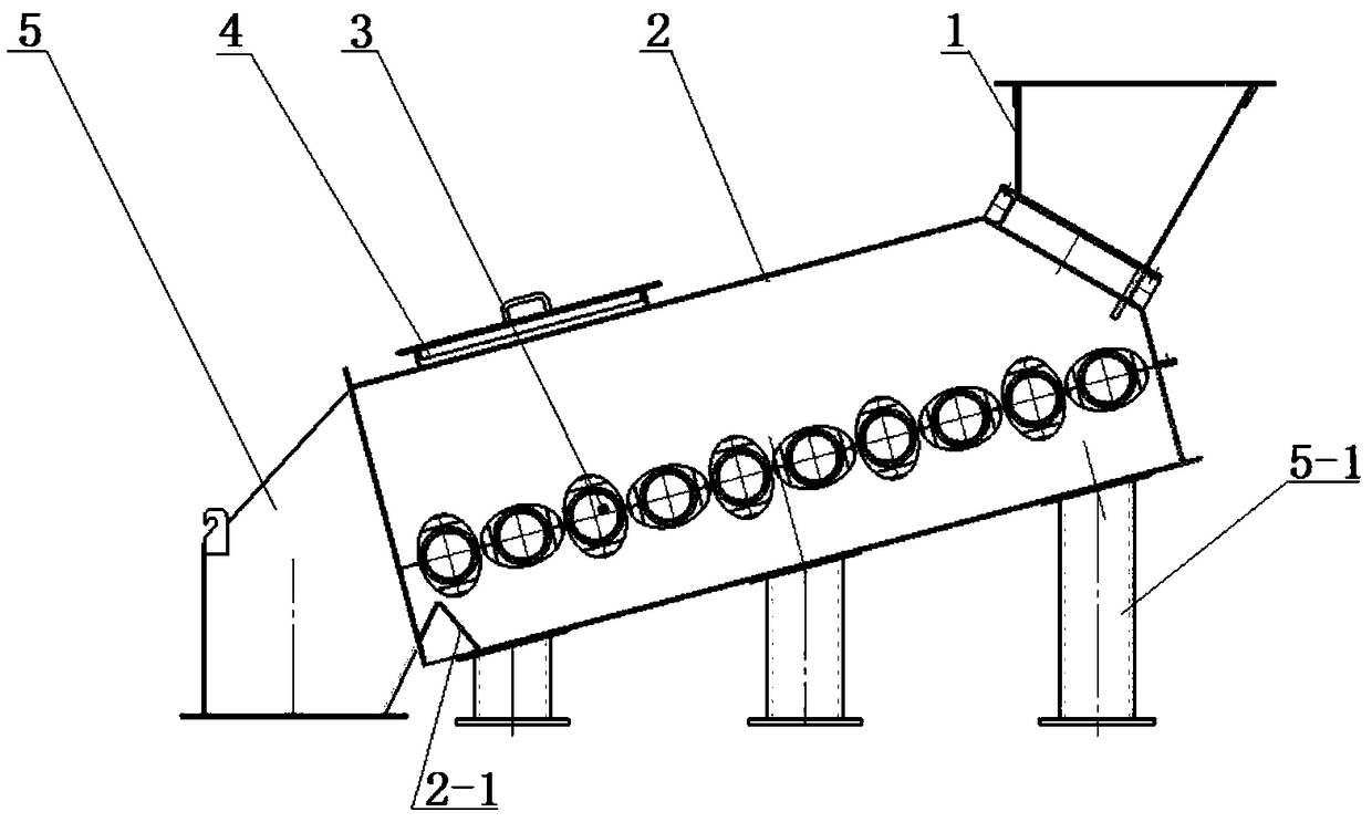
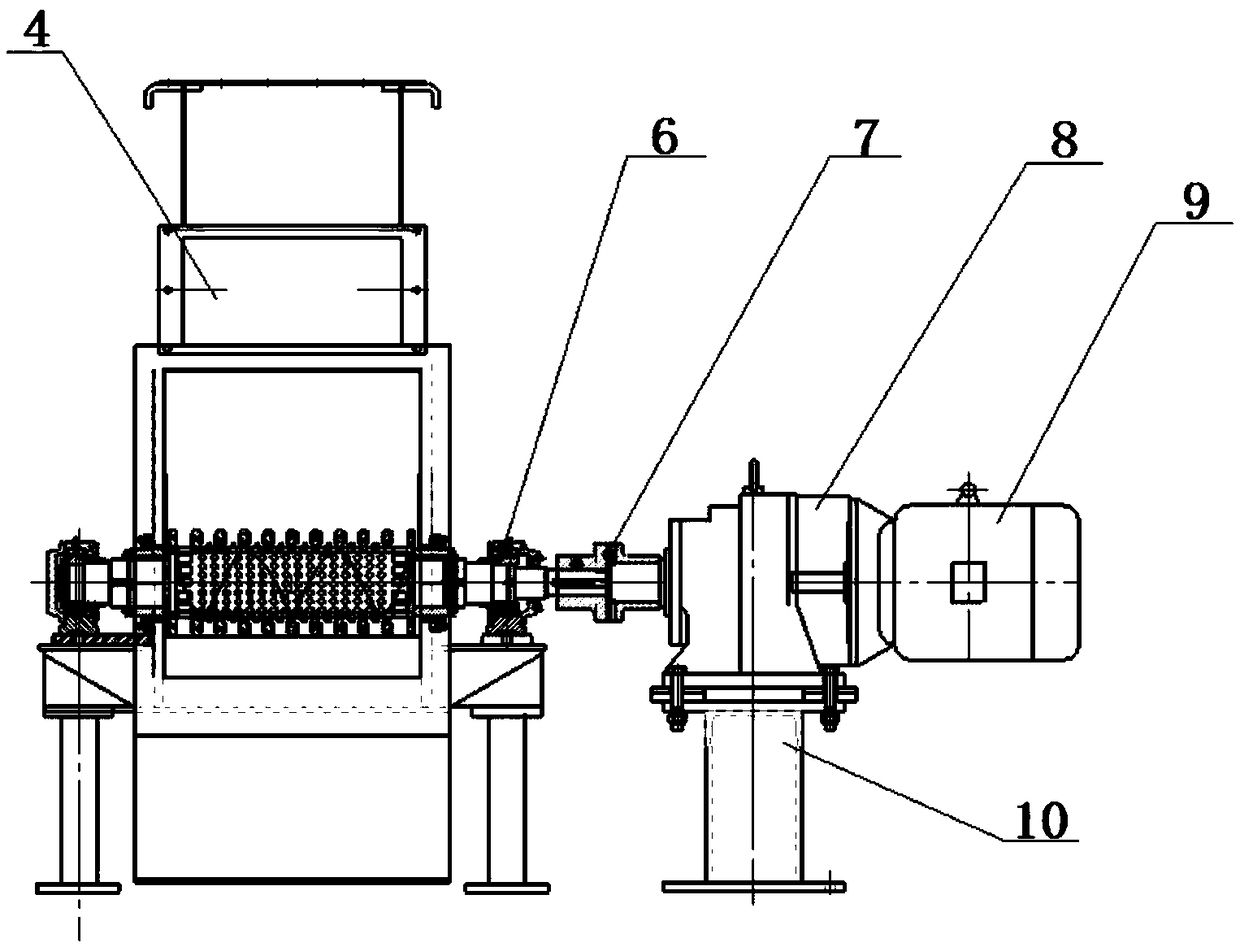
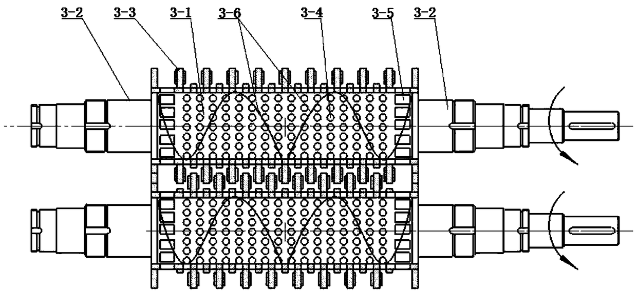
[0026] In this example, if Figure 1-4 As shown, a large screen surface screening machine includes a body and a power control machine; the body includes a feed inlet 1, a screening chamber 2, a coarse material discharge port 5 and a fine material discharge port 5-1; the described The screening chamber 2 is arranged obliquely and is provided with a feed port 1 and a coarse material discharge port 5 respectively at both ends, and the feed port 1 is located at a height of the coarse material discharge port 5; the bottom surface of the screening chamber 2 is formed by The feed port 1 to the coarse material discharge port 5 are arranged inclined downwards and the bottom surface is evenly arranged with a plurality of fine material discharge ports 5-1, and the bottom end of the ...


PUM


Abstract

The invention discloses a screening machine with a large screening area. The screening machine comprises a machine body and a power control machine; the machine body comprises a feeding inlet, a screening cavity, a coarse material discharging outlet and a plurality of fine material discharging outlets; the screening cavity is internally provided with a plurality of screening rollers, and the multiple screening rollers are obliquely arranged from the top end to the bottom end of the screening cavity; the included angle between every two adjacent screening rollers is 90 degrees; each screening roller comprises a screening barrel, a plurality of first screening holes, a rotary shaft, a plurality of elliptical screening sheets, a plurality of second screening holes and a guide sheet; and the top of the screening cavity is provided with a plurality of automatic material distribution devices. According to the screening machine with the large screening area, compared with traditional screening machines, the screening area is larger, the material blockage, locking and adhesion possibility is reduced, the screening efficiency and quality are improved, and noise is lowered.

Description

technical field [0001] The invention belongs to the field of screening machine equipment, and in particular relates to a large screening surface screening machine. Background technique [0002] The process in which the broken material is divided into different particle sizes through one or several layers of sieve surface is called sieving. The screening machine is a vibrating screening machine that uses the relative movement between the bulk material and the screen surface to make some particles pass through the screen holes, and divide sand, gravel, crushed stone and other materials into different grades according to the particle size. It can be widely used in material thickness. Separated industries such as coal, ore, power generation, chemical industry, coking, steel, paper, grain and metal, etc. The screening process of the sieving machine is generally continuous. After the sieving raw materials are fed to the screening machine (referred to as the sieve), the material s...

Claims


Application Information

Patent Timeline
IPC IPC(8): B07B1/15B07B1/46B02C23/08B02C13/26
CPCB02C13/26B02C23/08B07B1/15B07B1/4609Y02W30/62
Inventor 曹刚李寿海鲜红梅姜伟左明志吴杰
Owner 四川皇龙智能破碎技术股份有限公司
Learn More