Composite screen and material screening method

A sieve and material technology, applied in the field of composite sieves and sieving materials, can solve the problems of not being able to enter the sieve cavity, the material cannot be discharged in time, and the screening efficiency is reduced, so as to improve the kinetic energy of loosening, improve the kinetic energy of penetrating sieves, and improve screening. The effect of efficiency

Pending Publication Date: 2020-09-01
常州国岱选煤科技有限公司
View PDF0 Cites 1 Cited by
  • Summary
  • Abstract
  • Description
  • Claims
  • Application Information

AI Technical Summary

Problems solved by technology

[0004] The disadvantages of strong vibration screening technology are: large vibration load and high noise;
[0005] The disadvantage of the cross roller screening technology is: the screen surface structure of the cross roller screen is composed of a circular screen on the shaft to form a dome surface and a trapezoidal screen cavity formed by the cross arrangement of the upper and lower shaft screens, which is smaller than the screen. The material with the width of the cavity falls into the sieve cavity, and the material smaller than the sieve gap falls into the bottom of the sieve to achieve the purpose of screening; the material smaller than the width of the sieve cavity and greater than the width of the sieve gap is carried out of the sieve cavity in the sieve cavity by the friction of the sieve. Conveying in the direction of the outlet
[0006] Since the sieve chamber is a trapezoidal cross-section, which is equivalent to a falling pit, the remaining materials are brought out entirely by the friction of the sieve, so the efficiency of materials being discharged from the sieve chamber is very low, and the old materials cannot be discharged in time, and the new materials are If it cannot enter the sieve chamber, effective screening cannot be carried out, especially when the particle size composition of the material is fine, the screening efficiency will drop significantly

Method used


Image

  • Composite screen and material screening method
  • Composite screen and material screening method
  • Composite screen and material screening method

Examples


Embodiment Construction

[0035] The following will clearly and completely describe the technical solutions in the embodiments of the present invention. Obviously, the described embodiments are only some of the embodiments of the present invention, rather than all the embodiments. Based on the embodiments of the present invention, all other embodiments obtained by persons of ordinary skill in the art without making creative efforts belong to the protection scope of the present invention.

[0036] see Figure 1 to Figure 6 , the embodiment of the present invention includes:

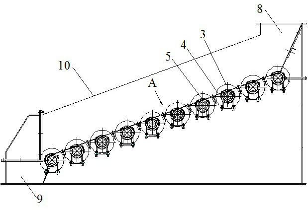
[0037] A compound sieve is located in a screening room 10. One side of the screening room 10 has a material inlet 8, and the other side has a material outlet 9. The screening room 10 is provided with a compound sieve arranged in an inclined manner.

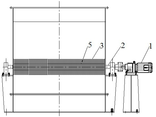
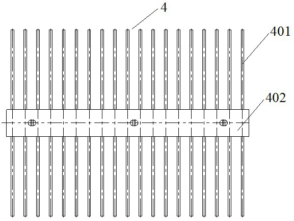
[0038] In the present invention, the composite sieve includes a circular screen 3, a ratchet 5, a drive shaft 2 and a spring sieve plate 4, the circular screen 3 and the ratchet 5 are...


PUM


Abstract

The invention discloses a composite screen and a material screening method. The composite screen comprises circular screen pieces, ratchet wheels, a driving shaft and spring screen plates, wherein thecircular screen pieces and the ratchet wheels are alternately connected to the driving shaft in series, the spring screen plates and the circular screen pieces are arranged in a crossed mode to forma composite screen surface, materials enter a screening chamber, materials smaller than first-stage screen cuts fall onto the spring screen plates, materials larger than the first-stage screen cuts flow to a discharging port, and primary material sieving is achieved; and materials smaller than second-stage screen cuts on the spring screen plates fall below the composite screen surface, materials larger than the second-stage screen cuts flow to the discharging port along the inclined screen surface formed by the spring screen plates, and meanwhile the composite screen surface generates periodicvibration along with rotation of the ratchet wheels, so that the materials obtain additional kinetic energy perpendicular to the screen surface. By means of the mode, the composite screen and the material screening method can improve the material loosening kinetic energy, wet and sticky materials can be well loosened, the screening penetrating kinetic energy of fine materials is improved, the screening efficiency is improved, and the good screening effect on coal, ore and fine wet and sticky materials is achieved.

Description

technical field [0001] The invention relates to the technical field of coal mine screening, in particular to a composite screen and a screening material method. Background technique [0002] With the improvement of the modern production level of coal mines, the important position of coal particle size classification in the coal production system has become increasingly prominent. Designing and manufacturing high-efficiency screening equipment to meet production needs can improve the classification level and efficiency of coal. It is fine particle size classification. Problems to be solved in technological development. [0003] Dry screening for coal, ore and other materials is mainly used to classify materials with a particle size of less than 6mm. In the prior art, strong vibration screening technology or cross roller screening technology is mainly used. [0004] The disadvantages of strong vibration screening technology are: large vibration load and high noise; [0005] ...

Claims


Application Information

Patent Timeline
IPC IPC(8): B07B1/34B07B1/42B07B1/46
CPCB07B1/343B07B1/42B07B1/46
Inventor 吴国宪陈欢吴苏川
Owner 常州国岱选煤科技有限公司
Why Eureka
Try Eureka