Optical fiber link monitoring system and method for passive optical fiber network

An optical fiber link and monitoring system technology, applied in transmission systems, electromagnetic wave transmission systems, electrical components, etc., can solve problems such as difficulty in distinguishing faults, ineffective interpretation of optical time domain reflectors, etc., to shorten the maintenance time.

Inactive Publication Date: 2011-08-31
刘超 +3
View PDF0 Cites 0 Cited by
  • Summary
  • Abstract
  • Description
  • Claims
  • Application Information

AI Technical Summary

Problems solved by technology

However, optical time domain reflectors cannot effectively interpret such figure 1 and figure 2 The state of a tree-like passive fiber optic network shown, as it is difficult to distinguish faults occurring at the ends of the tree-like network architecture

Method used


Image

  • Optical fiber link monitoring system and method for passive optical fiber network
  • Optical fiber link monitoring system and method for passive optical fiber network
  • Optical fiber link monitoring system and method for passive optical fiber network

Examples


Embodiment Construction

[0040] A detailed description of some embodiments of the invention follows, however, the invention can be practiced broadly in other embodiments beyond this detailed description. That is to say, the scope of the present invention is not limited by the proposed embodiments, but should be based on the patent scope of the present invention.

[0041] Moreover, in order to provide a clearer description and a better understanding of the present invention, the various parts in the diagrams are not drawn according to their relative sizes, and some sizes have been exaggerated compared with other relevant scales; irrelevant details are not completely drawn to keep the icons simple.

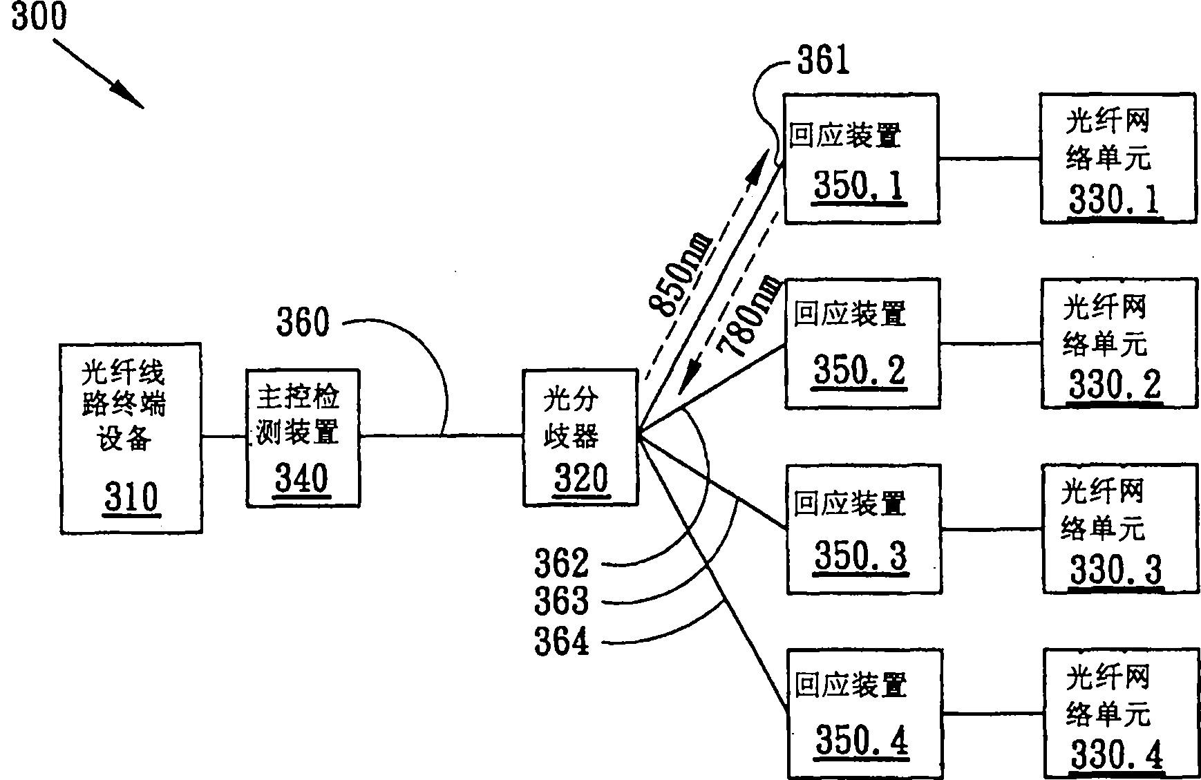
[0042] image 3 A schematic diagram showing the architecture of an optical fiber network system 300 with an optical fiber link monitoring function according to an embodiment of the present invention, which includes an optical fiber line terminal device 310, a main control monitoring device 340, an optical ...


PUM


Abstract

The invention provides an optical fiber link monitoring system of a passive optical fiber network, which comprises a main control monitoring device connected with an OLT end of optical fiber link terminal equipment and a plurality of response devices connected with an ONU end of an optical fiber network unit. The main control monitoring device applies time division multiplexing technique to order the response devices to send response optical signals in sequence and judge the link status by measuring the power of the response optical signals. The invention also provides a method for monitoring the optical fiber link of the passive optical fiber network. The system and method of the invention can supplement the shortages such as an optical time domain reflect meter in the prior art, monitor and record the quality of optical fiber transmission so as to replace the deteriorated optical fiber in time, and judge the broken-down line section in time and shorten the overhaul time when a sudden break of optical fiber cable happens.

Description

technical field [0001] The present invention relates to a passive optical network (Passive Optical Network, PON) monitoring technology, in particular to using Time Division Multiplexing (TDM) technology on the passive optical network to make each optical network unit (Optical Network Unit, ONU) Sequence response to monitor the quality of fiber optic links. Background technique [0002] Due to the characteristics of large capacity, high reliability and long transmission distance, optical fiber has gradually become the backbone of telecommunication links. The service of directly transmitting data to the client through optical fiber will be the mainstream of broadband link applications in the future, for example, Fiber To The Cabinet (FTTCab), Fiber To The Curb (FTTC), Fiber To the building (Fiber To The Building, FTTB) and fiber to the home (Fiber To The Home, FTTH), the above services can be collectively referred to as FTTx. Passive Optical Network (PON) is based on passive...

Claims


Application Information

Patent Timeline
Patent Type & Authority Patents(China)
IPC IPC(8): H04B10/12H04B10/08H04B10/077
Inventor 卢天祥
Owner 刘超
Why Eureka
Try Eureka