Non-cylindrical RF coil for MRI

A non-cylindrical, radio frequency coil technology, used in measuring devices, measuring magnetic variables, instruments, etc., can solve problems such as limited number of design parameters and limitations

Inactive Publication Date: 2008-10-29
KONINKLIJKE PHILIPS ELECTRONICS NV
View PDF0 Cites 21 Cited by
  • Summary
  • Abstract
  • Description
  • Claims
  • Application Information

AI Technical Summary

Problems solved by technology

However, birdcage coils have a limited number of design parameters, such as the number of spokes, coupling reactance between spokes and end rings, etc., which limits how well a birdcage coil design can counteract uneven coil loading

Method used


Image

  • Non-cylindrical RF coil for MRI
  • Non-cylindrical RF coil for MRI
  • Non-cylindrical RF coil for MRI

Examples


Embodiment Construction

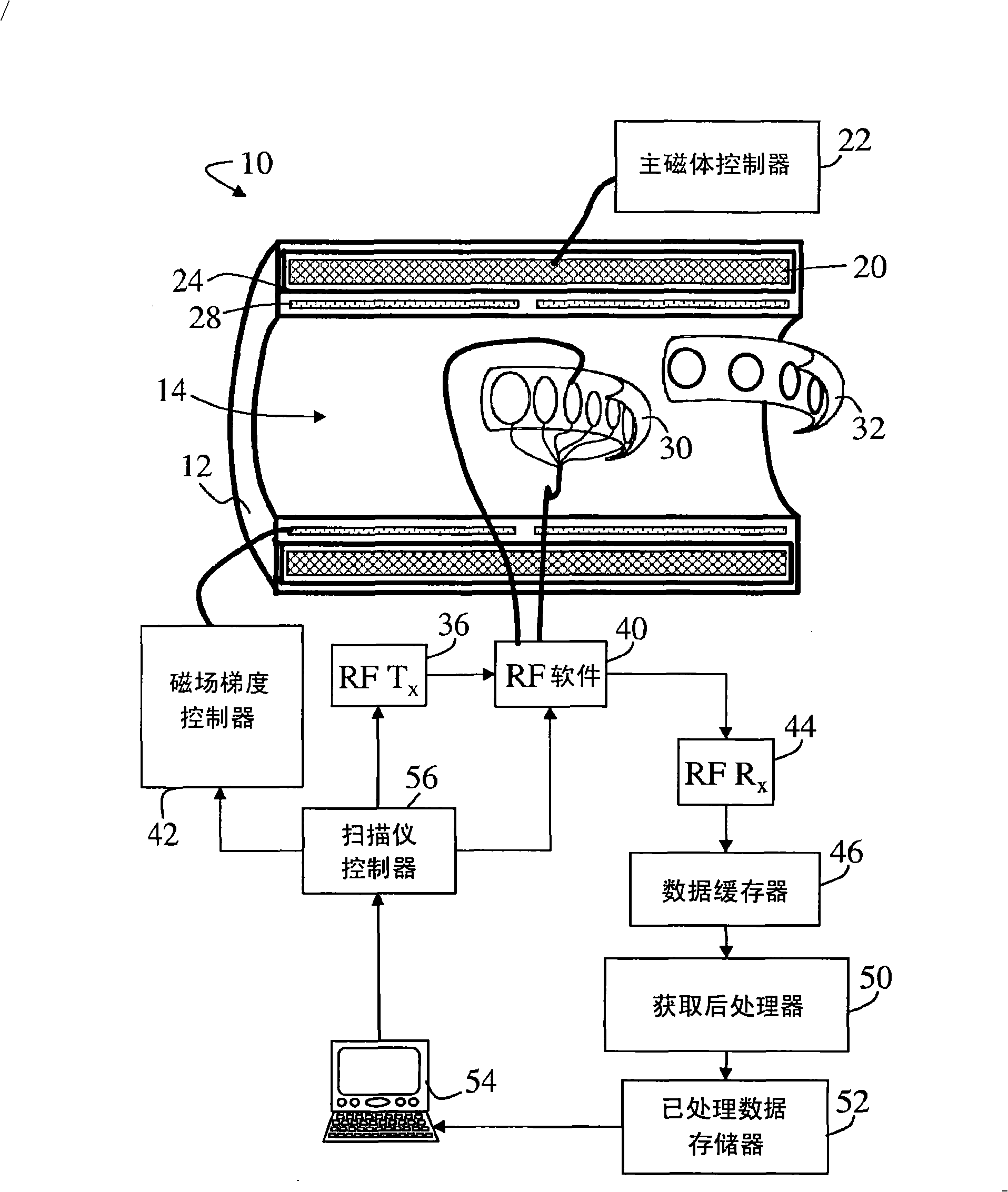
[0024] refer to figure 1 A magnetic resonance scanner 10 includes a scanner housing 12 that includes a cavity 14 or other receiving area for receiving a patient or other object. The main magnet 20 located in the scanner housing 12 is controlled by a main magnet controller 22 to generate a main B at least in the target area of ​​the cavity 14. 0 magnetic field. Typically, the main magnet 20 is a permanent superconducting magnet surrounded by a cryogenic cover 24, but a resistive main magnet could also be used.

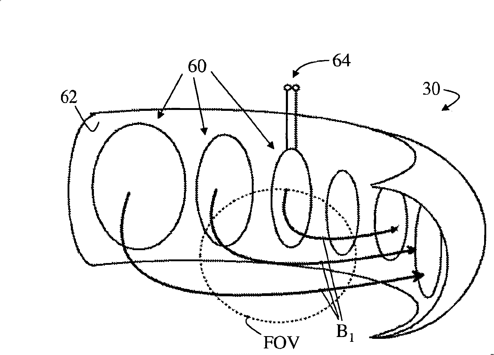
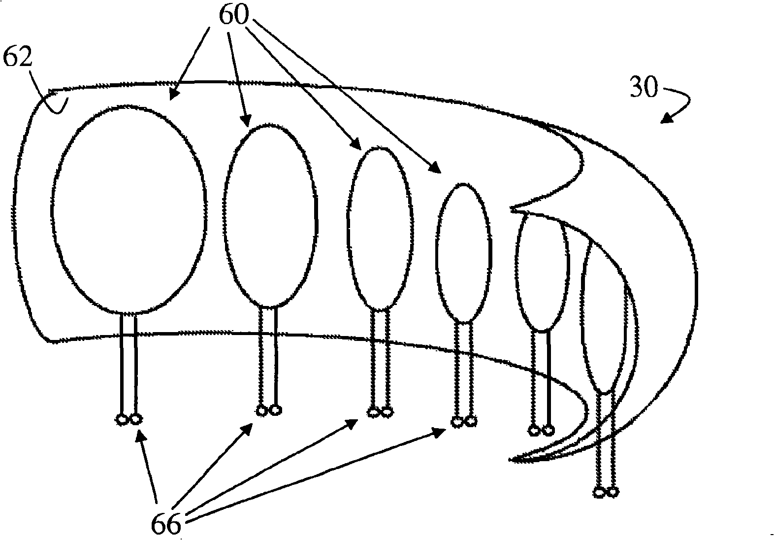
[0025] Magnetic field gradient coils 28 are arranged in or on housing 12 in order to superimpose selected magnetic field gradients at least on the main magnetic field in the relevant region. Typically, the magnetic field gradient coils include coils for generating three orthogonal magnetic field gradients (eg, x-gradient, y-gradient, and z-gradient). A radio frequency coil 30 is arranged within the cavity 14 of the scanner 10 for transmitting B 1 RF excitation pulse...


PUM


Abstract

A radio frequency coil includes a non-cylindrical conformal surface (62, 76) that substantially conforms with a magnetic resonance subject. A plurality of conductor loops (60, 71, 72, 73, 74) are disposed in or on the non-cylindrical conformal surface. The plurality of conductor loops are configured to produce a substantially uniform Bi field in the magnetic resonance subject responsive to energizing at a Bi frequency. Optionally, a plurality of load-compensating conductor loops (90) are disposed in or on a compensatory non-cylindrical conformal surface (62) that substantially conforms with a magnetic resonance subject. The plurality of load-compensating conductor loops are configured to produce a non-uniform Bi field that compensates for a loading Bi non-uniformity caused by the magnetic resonance subject. Moreover, the coil may comprise switching means for switching the coil between a first mode of operation (e.g. a volume transmit mode) and a second mode of operation (e.g. a phased array reception mode).

Description

technical field [0001] The invention relates to the field of magnetic resonance. The present invention is specifically used in radio frequency coils for magnetic resonance imaging, and the following will be described in conjunction with this point. Broadly speaking, the invention finds use in magnetic resonance imaging, magnetic resonance spectroscopy, and other magnetic resonance applications. Background technique [0002] In bore MRI scanners, the transmit coil is usually a birdcage coil comprising a plurality of cylindrically arranged rungs and terminated by end rings, end caps or the like. Under radiofrequency excitation at the magnetic resonance frequency, these coils generate a rotation B 1 A magnetic field that is substantially uniform within the imaging tube within the birdcage coil. In a whole-body coil, the cylindrical birdcage coil is usually aligned coaxially with the bore of the magnetic resonance scanner and excites a large volume. For specific applications...

Claims


Application Information

Patent Timeline
Patent Type & Authority Applications(China)
IPC IPC(8): G01R33/3415
CPCG01R33/3415G01R33/34084G01R33/3642G01R33/34046
Inventor J·魏岑埃克C·施罗德
Owner KONINKLIJKE PHILIPS ELECTRONICS NV
Why Eureka
Try Eureka