Supercharge Your Innovation With Domain-Expert AI Agents!

Method and system for automatic adjustment of a diagnostic imaging display

A diagnostic imaging and display technology, which is applied to radiological diagnostic instruments, diagnostics, and acoustic wave diagnostics, and can solve the problem that ultrasonic images will not be displayed optimally

Inactive Publication Date: 2008-11-05
GENERAL ELECTRIC CO
View PDF4 Cites 13 Cited by
  • Summary
  • Abstract
  • Description
  • Claims
  • Application Information

AI Technical Summary

Problems solved by technology

However, since these screens are usually optimized for displaying images over a very large display field, ultrasound images are often not displayed optimally and may be displayed below acceptable viewing levels, especially due to often present in these types of images due to the generally darker grayscale

Method used


Image

  • Method and system for automatic adjustment of a diagnostic imaging display
  • Method and system for automatic adjustment of a diagnostic imaging display
  • Method and system for automatic adjustment of a diagnostic imaging display

Examples


Embodiment Construction

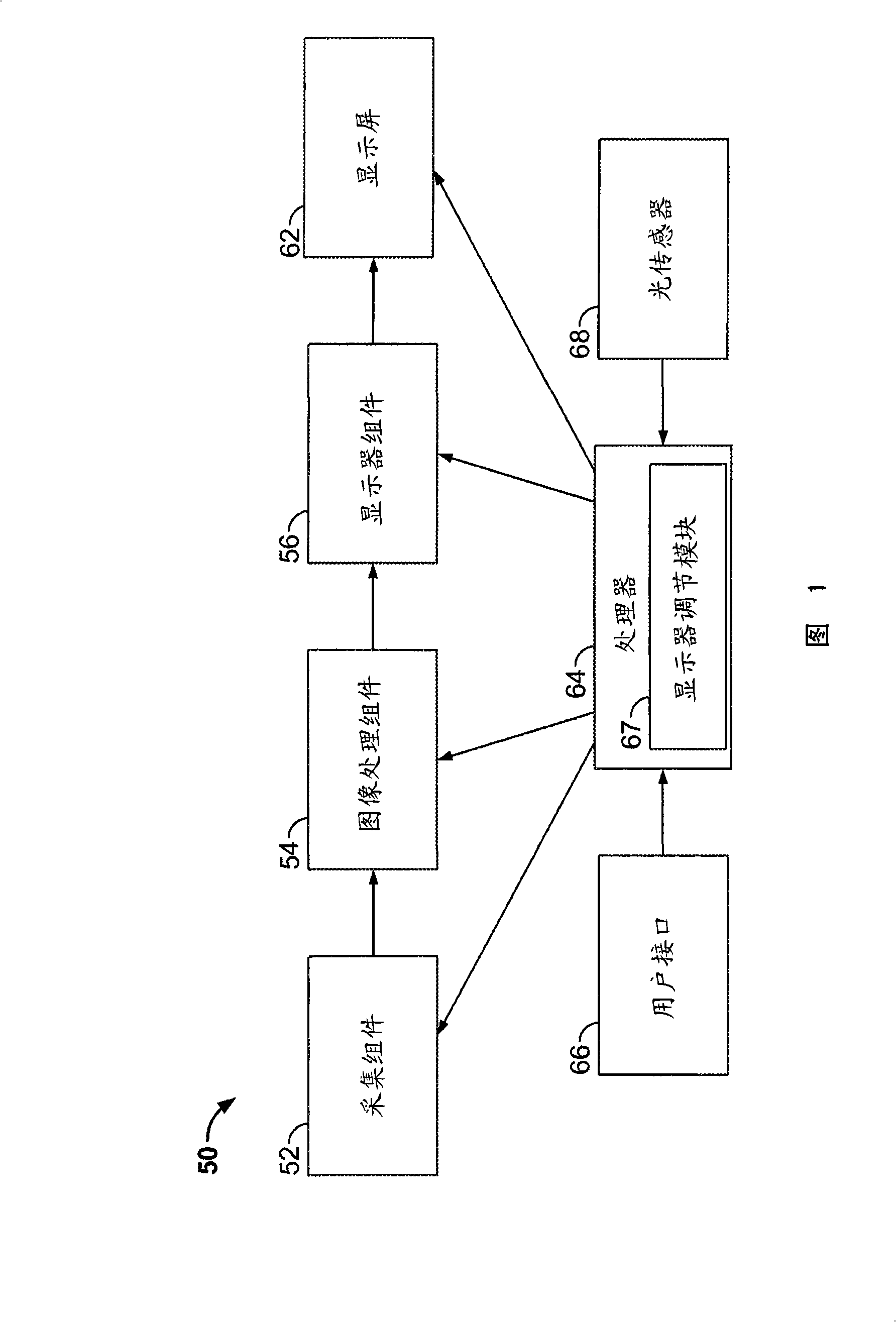
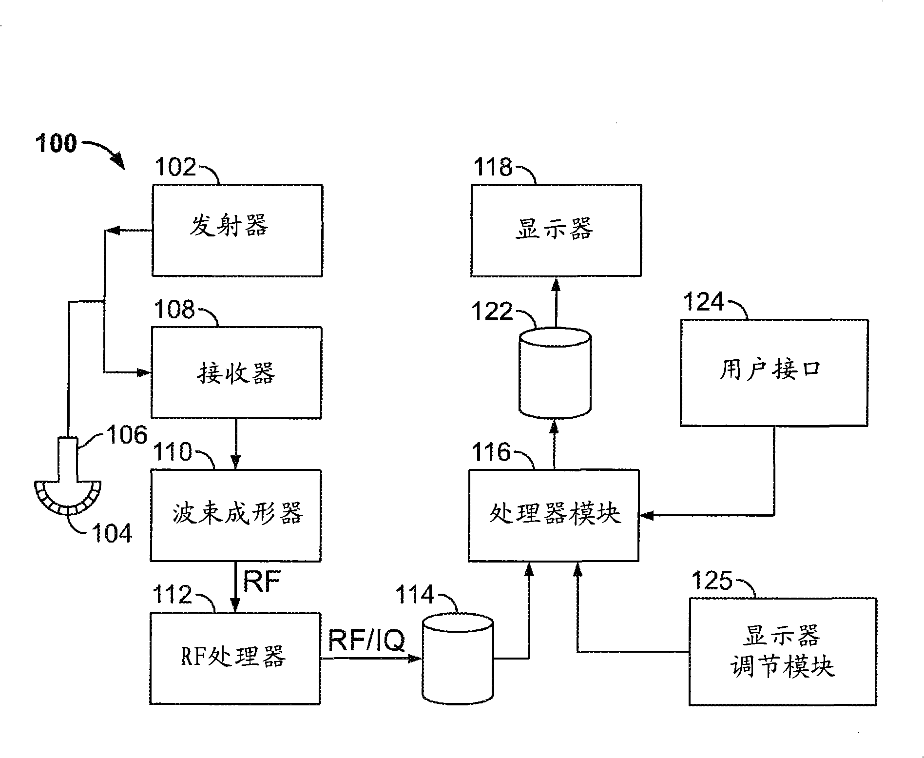
[0028] A better understanding of the foregoing summary and the following detailed description of certain embodiments of the present invention can be better understood by reading in conjunction with the accompanying drawings. To the extent that the drawings show diagrams of functional blocks of various embodiments, the functional blocks do not necessarily represent the division between hardware circuits. Therefore, for example, one or more of the functional blocks (such as a processor or a memory) may be implemented in a single hardware (such as a general-purpose signal processor or a random access memory block, a hard disk, etc.). Similarly, the program may be an independent program, or may be incorporated into the operating system as a subroutine, or may be a function in an installed software package, and so on. It should be understood that the embodiments are not limited to the arrangements and means shown in the drawings.

[0029] Unless specifically excluded otherwise, an elem...


PUM


Abstract

A method and system for automatic adjustment of a diagnostic imaging display are provided. The system includes an acquisition component configured to acquire image data and a display configured to display the acquired image data. The diagnostic imaging system further includes an ambient light detector configured to detect an ambient light level and a display adjustment module configured to automatically adjust a display transfer function for the display based on the detected ambient light level.

Description

Technical field [0001] The present invention generally relates to a diagnostic imaging system, and more specifically, to automatically adjusting the display settings of the display of the diagnostic imaging system. Background technique [0002] Diagnostic imaging systems, especially medical imaging systems, are used to image patients under many different conditions. For example, medical imaging scanners can be used to perform imaging in different rooms with different lighting conditions, such as daylight or bright light in one room, and low light or dark in another room. The surrounding ambient light affects the image displayed on the screen of the medical imaging system. As medical imaging systems continue to become more portable or more mobile, the operating conditions of the system will change more frequently, such as when moving the mobile system from one room or location to another room or location The operating conditions will change. [0003] Users often neglect to readjus...

Claims


Application Information

Patent Timeline
Patent Type & Authority Applications(China)
IPC IPC(8): A61B19/00A61B8/00G09G5/10G09G3/20G09G3/36
CPCA61B8/461A61B5/7445H04N5/58A61B6/461G06F19/3406A61B8/467G16H40/63
Inventor A·索库林R·梅尼罗姆D·赫斯M·艾曾
Owner GENERAL ELECTRIC CO
Features
  • R&D
  • Intellectual Property
  • Life Sciences
  • Materials
  • Tech Scout
  • Unparalleled Data Quality
  • Higher Quality Content
  • 60% Fewer Hallucinations
Learn More