Cable protective guiding apparatus

A guiding device and cable technology, which is applied in the installation of cables, the arrangement of cables between relatively moving parts, and the direction of drag chains, etc., can solve the problems of increasing the burden of connecting and assembling chain parts, and the complicated and difficult structure of metal molds.

Active Publication Date: 2011-05-18
TSUBAKIMOTO CHAIN CO
View PDF5 Cites 0 Cited by
  • Summary
  • Abstract
  • Description
  • Claims
  • Application Information

AI Technical Summary

Problems solved by technology

[0004] However, in the energy supply chain as in Patent Document 1, as shown in FIG. 12 , the stopper 511 provided on the side plate 510 in order to limit the rotational movement of the chain members is located in both the thickness direction of the side plate 510 and the direction of the inner and outer peripheral sides of the curve. There is a three-dimensional concave-convex protrusion on the top, and the fan-shaped recess 512 that accommodates the stopper 511 presents a three-dimensional concave-convex hook in both the thickness direction of the side plate and the direction of the inner and outer peripheral sides of the bend, so although it is considered To the anti-off structure with the adjacent chain members, but the stopper 511 presenting such a 3-dimensional concave-convex protrusion and the fan-shaped recess 512 presenting a 3-dimensional concave-convex hook are used to manufacture the side plate 51 The die-drawing structure of the metal mold becomes complicated and difficult, and there is a troublesome problem that the burden of connecting and assembling the chain parts during the chain assembly is significantly increased.

Method used


Image

  • Cable protective guiding apparatus
  • Cable protective guiding apparatus
  • Cable protective guiding apparatus

Examples


Embodiment Construction

[0027] Therefore, a cable protection and guide device as an embodiment of the present invention will be described below with reference to FIGS. 1 to 8 .

[0028] 【Example】

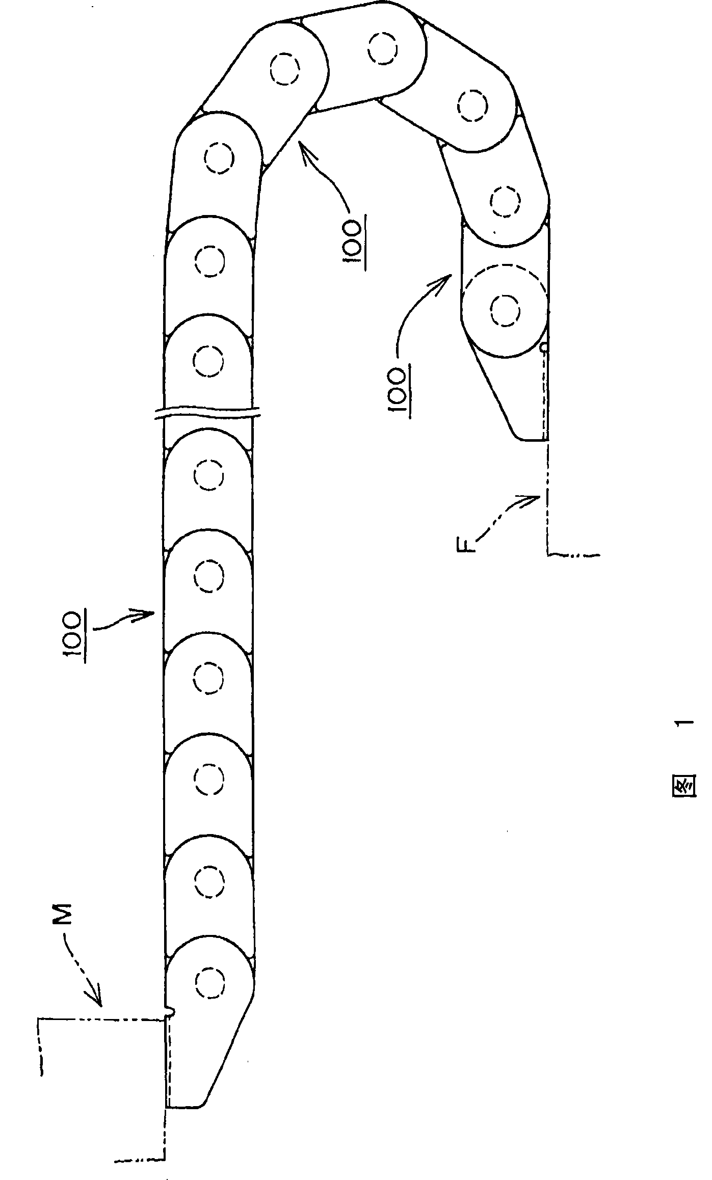
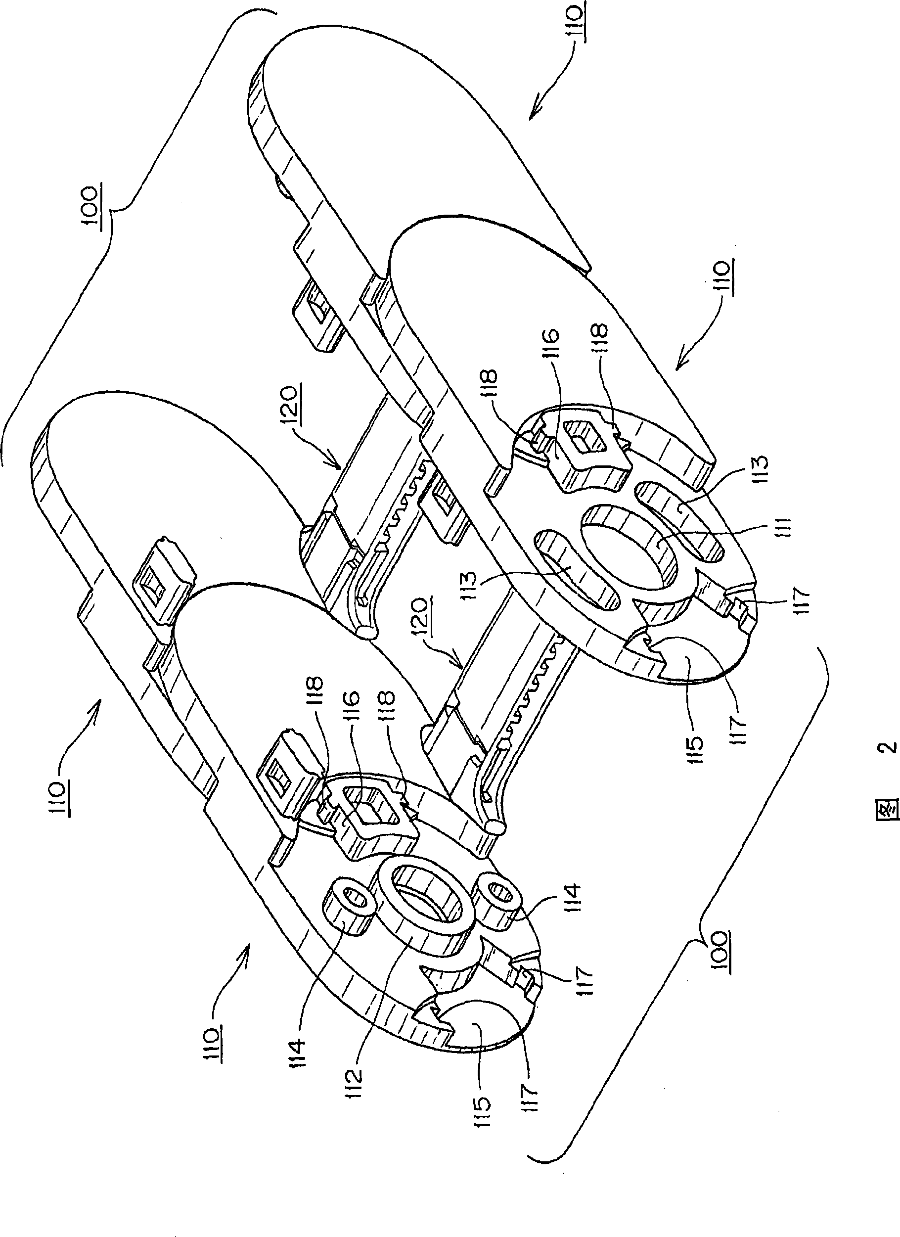
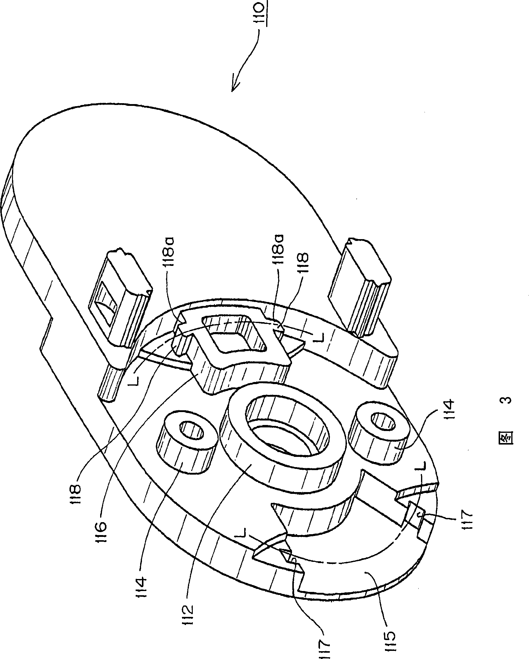
[0029] First of all, Fig. 1 is a diagram showing the use of a cable protection and guiding device according to an embodiment of the present invention, Fig. 2 is a perspective view showing the connection state of the link plates in Fig. The perspective view of the link plate used in this embodiment, FIG. 4 is a perspective view of the link plate shown in FIG. 3 viewed from the outside of the cable storage space, and FIG. 5 is the connected state of the link plate from the side of the cable storage space Partial cut-away perspective view, FIG. 6 is a partially cut-away perspective view of the connected state of the link plate from the outside of the cable storage space, and FIG. 7 is a partially cut-away perspective view showing the main part that restricts warpage. FIG. 8 9 is a perspective view of the str...


PUM


Abstract

A cable protection and guide device, wherein: the warp in front and rear side portions of link plates in the width direction is reliably limited so that an inadvertent disengagement between the link plates is completely blocked. The connection between the link plates is easy and manufacturing of the link plates is easy. Short arc-shaped warp limiting lock grooves are formed along a path coaxiallyspaced from a connecting pin or a connecting pin hole. Short arc-shaped warp limiting lock pieces are fitted to the short arc-shaped warp limiting lock grooves in a concave element / convex element engagement opposed surfaces of the link plates connected in the longitudinal direction so that warping in the front and rear side portions of the link plates in a width direction is limited.

Description

technical field [0001] The present invention relates to safe and reliable protection and guidance of electric cables for power supply, signal transmission, etc., used in industrial machines such as machine tools, electronic equipment, industrial robots, and conveying machines, etc. Cable protection and guide devices for flexible cables such as oil pressure hoses, air pressure hoses, and optical fiber cables. Background technique [0002] Conventionally, as such a cable protection and guide device, there is an energy supply chain for accommodating cables, pipes, etc.: the chain member is formed in a box shape, and plugs and circular openings are alternately provided on the side wall. The plug of the chain member fits into the opening of the next chain member and the relative rotational movement of the successive chain member is restricted by the stopper 511 of the side wall portion of the successive chain member (for example, refer to Patent Document 1). [0003] [Patent Doc...

Claims


Application Information

Patent Timeline
Patent Type & Authority Patents(China)
IPC IPC(8): F16G13/16
CPCF16G13/16H02G11/00Y10S59/90
Inventor 小宫庄一郎
Owner TSUBAKIMOTO CHAIN CO
Why Eureka
Try Eureka