Coolant compressor

A technology for compressors and refrigerants, applied in mechanical equipment, machines/engines, liquid variable capacity machines, etc., can solve the problems of piston processing cost, high processing cost, uneconomical, etc., and achieve high torque and small structural size. Effect

Active Publication Date: 2011-06-01
ACC AUSTRIA GMBH
View PDF7 Cites 6 Cited by
  • Summary
  • Abstract
  • Description
  • Claims
  • Application Information

AI Technical Summary

Problems solved by technology

However, the machining of pistons of different sizes and diameters required here is complex and uneconomical
The precise final machining of the reamed piston bore in the region of the piston running surface also results in high machining costs

Method used


Image

  • Coolant compressor
  • Coolant compressor
  • Coolant compressor

Examples


Embodiment Construction

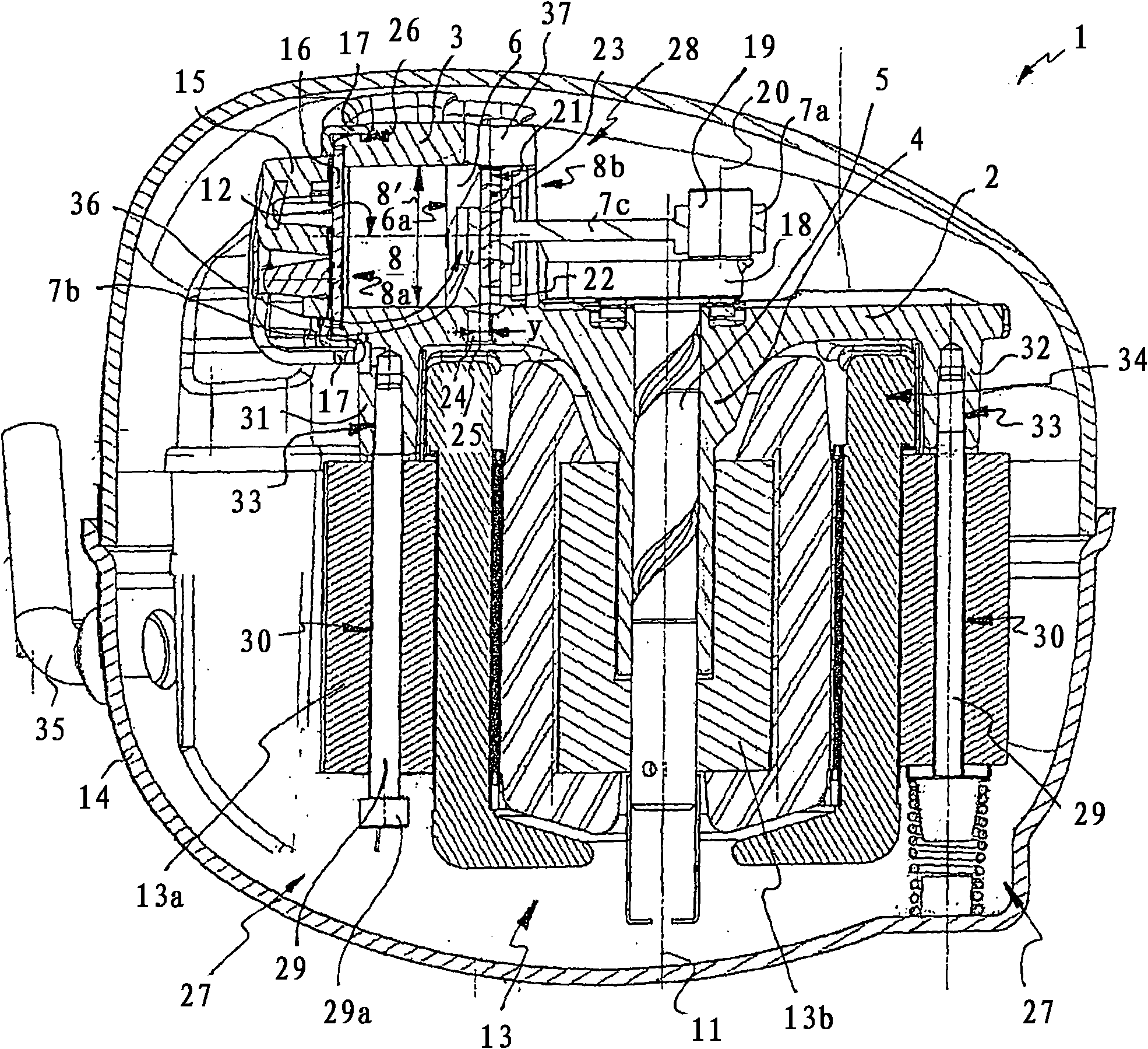
[0041] figure 1 A refrigerant compressor according to the invention is shown comprising a hermetically sealed compressor housing 14 . Arranged in the compressor housing 14 is an electric motor 13 , which is supported in the bottom region of the compressor housing 14 by means of an elastic bearing.

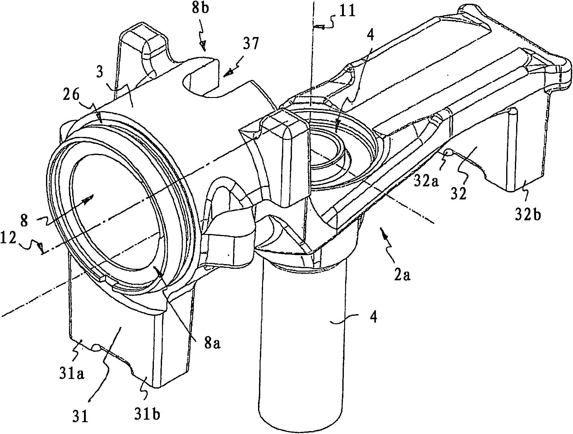
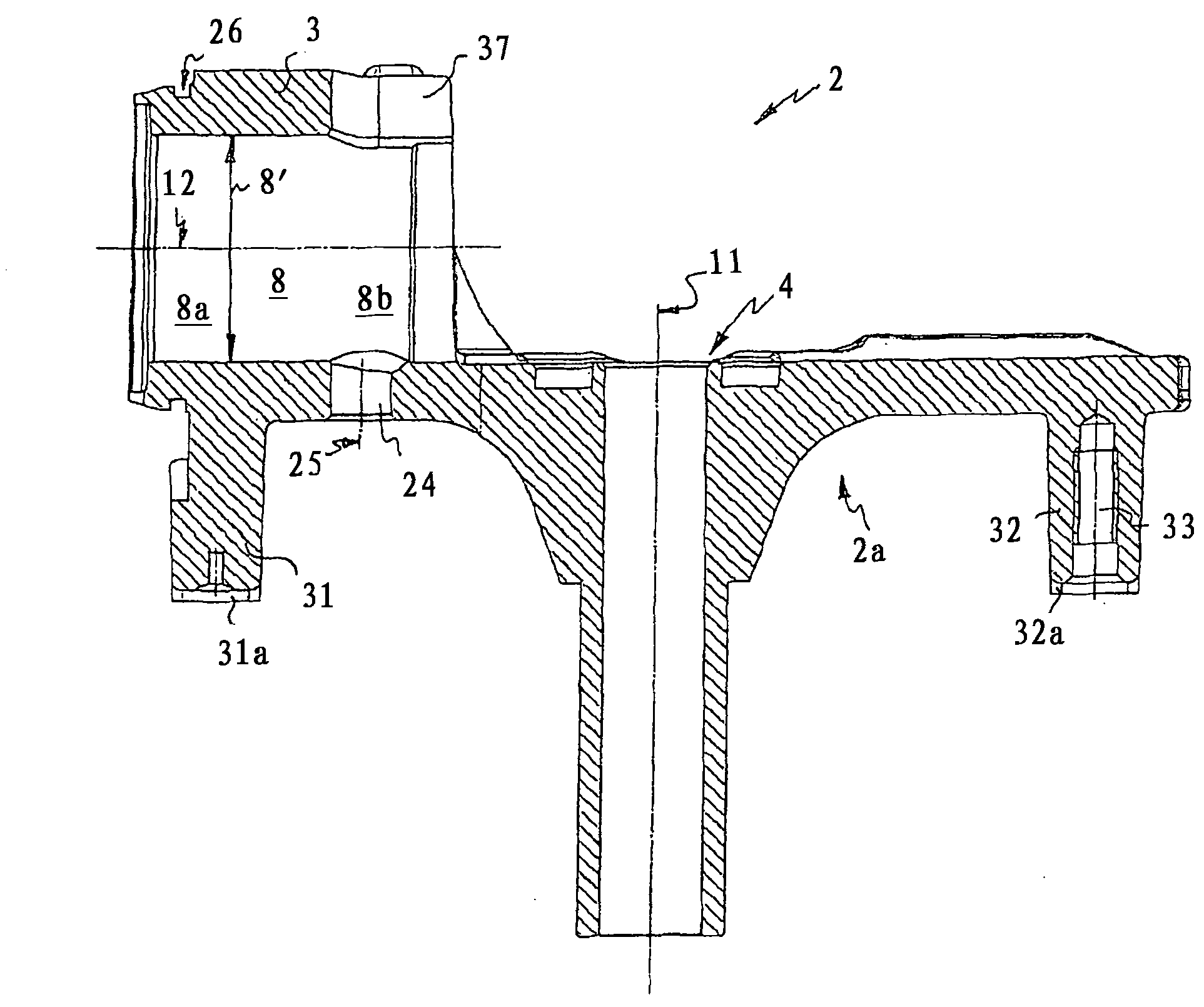
[0042] Mounted on the electric motor 13 is a bridge-shaped support body 2 , which is fastened to the stator 13 a of the electric motor 13 by means of screw elements 29 . exist figure 2 The supporting body 2 shown in a partial view spans the upper part of the motor winding 34 of the electric motor 13 (also referred to as "upper winding end") and has two mutually opposite foot elements 31 and 32, which are supported on the stator 13a . Each foot element 31, 32 has two abutments 31a, 31b or 32a, 32b on the end faces, so that the support body 2, which is formed narrowly, is therefore stably supported on the stator 13a on a total of four support surfaces (see press Figure 5 Bottom...


PUM


Abstract

Disclosed is a hermetically enclosed coolant compressor (1) comprising a cylinder housing (3) and a piston (6) which is guided along a defined piston bearing area (9) within a piston bore (8) of the cylinder housing (3) and is hinged, by means of a connecting rod (7), to a crankshaft (5) that is driven by an electric motor (13). The crankshaft (5) is mounted in a bearing element (2) that is preferably designed in a monolithic manner along with the cylinder housing (3). The piston bore (8) is closed by a cylinder head (15) encompassing a valve disk (16) in a first end region (8a) while being open for accommodating the piston (6) in a second end region (8b) facing the crankshaft (5). According to the invention, the piston bore (8) has a free-running section (10) that adjoins the piston bearing area (9) and is arranged in the second end region (8b) of the piston bore (8). The width (10') of the internal opening of the free-running section (8b) is greater than the diameter (9') of the piston bearing area (9) in order to prevent contact between the piston (6) and the cylinder housing (3) in said section.

Description

technical field [0001] The invention relates to a hermetically encapsulated refrigerant compressor according to the preamble of claim 1, comprising a cylinder housing and a piston guided along a defined piston working surface in a piston bore of the cylinder housing for compressing Working medium, said piston is articulated by means of a connecting rod on a crankshaft driven by an electric motor, wherein the crankshaft rotatable about an axis of rotation is mounted in a support body preferably formed in one piece with the cylinder housing, the piston bore at a first end The area is closed by a cylinder head including the valve plate, while the piston bore is open in the area of ​​a second end facing the crankshaft for receiving the piston. Background technique [0002] The operation of such refrigerators with zeotropen gases has been known for many years. where the refrigerant is heated in the evaporator by energy absorption from the space to be cooled and finally superheat...

Claims


Application Information

Patent Timeline
Patent Type & Authority Applications(China)
IPC IPC(8): F04B39/12
CPCF04B39/121F04B39/122F04B2201/0206
Inventor W·布拉贝克A·施魏格霍费尔S·兰普雷希特
Owner ACC AUSTRIA GMBH
Why Eureka
Try Eureka