Supercharge Your Innovation With Domain-Expert AI Agents!

Crank position correction using cylinder pressure

A technology of cylinder pressure and crankshaft position, applied in the direction of using fluid devices, electrical control, measurement devices, etc., can solve the problems of inaccurate engine speed and engine position calculation of crankshaft signals, inefficient operation of vehicle subsystems, etc.

Inactive Publication Date: 2010-08-11
GM GLOBAL TECH OPERATIONS LLC
View PDF0 Cites 0 Cited by
  • Summary
  • Abstract
  • Description
  • Claims
  • Application Information

AI Technical Summary

Problems solved by technology

Errors in the crankshaft signal can lead to inaccurate engine speed and engine position calculations, which can lead to inefficient operation of one or more vehicle subsystems

Method used


Image

  • Crank position correction using cylinder pressure
  • Crank position correction using cylinder pressure
  • Crank position correction using cylinder pressure

Examples


Embodiment Construction

[0014] The following description is merely exemplary in nature and is not intended to limit the present disclosure, application, or use. For purposes of clarity, the same reference numbers will be used in the drawings to refer to similar elements. The term "module" as used herein refers to an application-specific integrated circuit (ASIC), an electronic circuit, a processor (shared, dedicated, or group) and memory that executes one or more software or firmware programs, a combinational logic circuit, or provides the Other appropriate components of functionality.

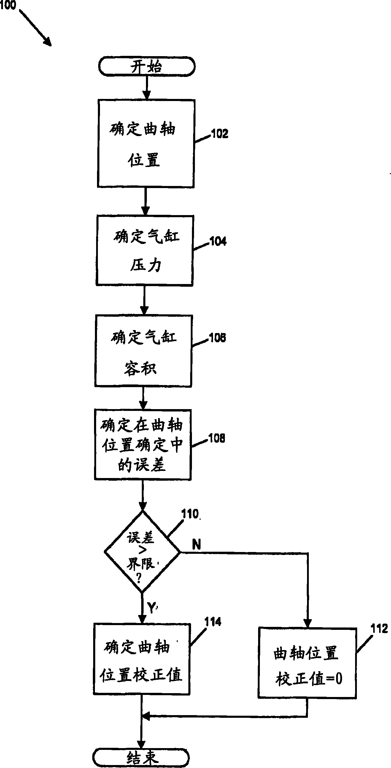
[0015] Referring to FIG. 1 , an exemplary vehicle 10 is schematically illustrated. The vehicle 10 may include an engine 12 and a control module 14 . Engine 12 may be a spark ignition internal combustion or diesel engine and may include a plurality of cylinders 16 having a plurality of pistons 18 disposed therein for reciprocating motion and drivingly engaged with a crankshaft 20 through a series of connecting rods 21...


PUM


Abstract

A method of correcting a crankshaft position may include determining first, second, and third crankshaft positions, determining first, second, and third cylinder pressures, determining first, second, and third cylinder volumes, determining the logarithm of the first, second, and third cylinder pressures and cylinder volumes, and determining a relationship between the third cylinder volume and thefirst and second cylinder volumes. The first, second, and third crankshaft positions may be provided during one of a piston expansion stroke and a piston compression stroke within a cylinder. The logarithm of the third cylinder pressure and cylinder volume may be evaluated with respect to a predetermined limit of a line defined by the logarithm of the first and second cylinder pressures and firstand second cylinder volumes.

Description

[0001] This application claims the benefit of U.S. Provisional Patent Application No. 60 / 919,555, filed March 23, 2007. The disclosures of the aforementioned applications are hereby incorporated by reference. technical field [0002] The present disclosure relates to engine systems, and more particularly to systems and methods for estimating crankshaft position. Background technique [0003] The statements in this section merely provide background information related to the present disclosure and may not constitute prior art. [0001] Certain vehicles include internal combustion engines that generate drive torque. More specifically, the engine takes in air and mixes the air with fuel to form a combustion mixture. The combustion mixture is compressed and ignited to drive a piston placed within the cylinder. Pistons drive the crankshaft that rotationally transmits drive torque to the transmission and wheels. [0004] A crankshaft position signal is generated based on rotation ...

Claims


Application Information

Patent Timeline
Patent Type & Authority Patents(China)
IPC IPC(8): G01B13/00G01M15/00G01M15/06F02D45/00
CPCG01M15/08F02D41/009F02D35/023G01M15/06
Inventor K·J·布斯勒普D·R·维尔纳
Owner GM GLOBAL TECH OPERATIONS LLC
Features
  • R&D
  • Intellectual Property
  • Life Sciences
  • Materials
  • Tech Scout
  • Unparalleled Data Quality
  • Higher Quality Content
  • 60% Fewer Hallucinations
Learn More