Voltage dependent resistor

A varistor, flame retardant plastic technology, applied in the direction of varistor, overvoltage protection resistor, etc., can solve the problems of low thermal efficiency, long operation time, slow transmission speed, etc., achieve large heat collection area, prevent aging, High thermal efficiency

Active Publication Date: 2008-11-12
THINKING ELECTRONIC IND CO LTD
View PDF1 Cites 10 Cited by
  • Summary
  • Abstract
  • Description
  • Claims
  • Application Information

AI Technical Summary

Problems solved by technology

There are problems in this patent: the heat is transferred to the top of the fuse with a long conduction path, slow transfer speed, and long disconnection time
There is a problem in this patent: the alloy fuse in the thermal fuse does not receiv

Method used


Image

  • Voltage dependent resistor
  • Voltage dependent resistor

Examples


Example Embodiment

[0018] The present invention will now be described in further detail with reference to the drawings and preferred embodiments. These drawings are all simplified schematic diagrams, which merely illustrate the basic structure of the present invention in a schematic manner, so they only show the structures related to the present invention.

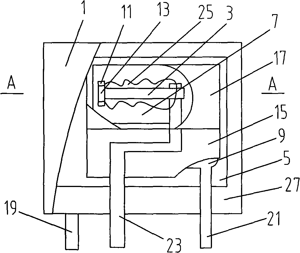
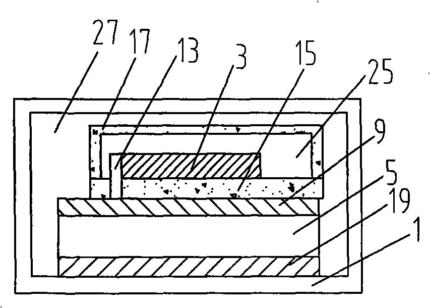
[0019] Such as Figure 1-2 The varistor shown includes a housing 1 in which a fuse 3 and a varistor 5 are arranged, an insulating layer 7 is arranged between the fuse 3 and the varistor 5, and the insulating layer 7 is connected to the The varistor 5 is connected by a high temperature metal through a metal conductor 9. Moreover, both ends of the varistor 5 are connected with a first pin 19 and a second pin 21, and the second pin 21 is connected to the varistor 5 through a metal conductor 9, and the insulating layer 7 is provided with a through hole 11. One end of the fuse 3 is connected to the metal conductor 9 through a metal pin 13 which passes...


PUM


Abstract

The invention relates to a fast-response thermal protection varistor, comprising a shell in which a fuse and a varistor are arranged. An insulating layer is arranged between the fuse and the varistor. The insulating layer is connected with the varistor by a metal conductor through high temperature metal. The fast-response thermal protection varistor ensures that the low temperature alloy fuse can sense the heat of the varistor directly and quickly. Furthermore, the fast-response thermal protection varistor has large collector area, short heat transfer path and high heating efficiency and effectively prevents the aging of the varistor.

Description

Technical field [0001] The invention relates to a zinc oxide varistor, in particular to a quick response thermal protection type varistor. Background technique [0002] In the existing technology, US Patent 6,636,403 provides a varistor with thermal protection function. One end of the fuse is directly soldered to the chip, and the other end of the fuse is connected to a metal wire, which is led out as the pin of the varistor. . A ceramic sheet is installed between the metal wire and the pressure-sensitive chip for insulation isolation. There is organic matter on the top of the fuse, and the working mechanism is: when the temperature of the pressure-sensitive chip increases, heat is conducted to the organic matter on the top of the fuse, and the organic matter is heated to expand, and the melted fuse is crushed. The patent has problems: the heat transfer to the organic matter on the top of the fuse has a long conduction path, a slow transfer speed, and a long disconnection time. I...

Claims


Application Information

Patent Timeline
IPC IPC(8): H01C7/12H01C7/10
Inventor 屠克俭高长安周垠群
Owner THINKING ELECTRONIC IND CO LTD
Why Eureka
Try Eureka