Electric hand control, especially for electrically adjustable hospital and care beds

An adjustable, nursing bed technology, used in hospital beds, hospital equipment, surgery, etc., can solve the problem of difficult to feel whether the switch is actuated or damaged

Inactive Publication Date: 2008-11-12
LINAK AS
View PDF2 Cites 1 Cited by
  • Summary
  • Abstract
  • Description
  • Claims
  • Application Information

AI Technical Summary

Problems solved by technology

Therefore, it is difficult to feel whether the switch is actuated, which makes many people roughly press these keys and cause damage to these keys and switches

Method used


Image

  • Electric hand control, especially for electrically adjustable hospital and care beds
  • Electric hand control, especially for electrically adjustable hospital and care beds
  • Electric hand control, especially for electrically adjustable hospital and care beds

Examples


Embodiment Construction

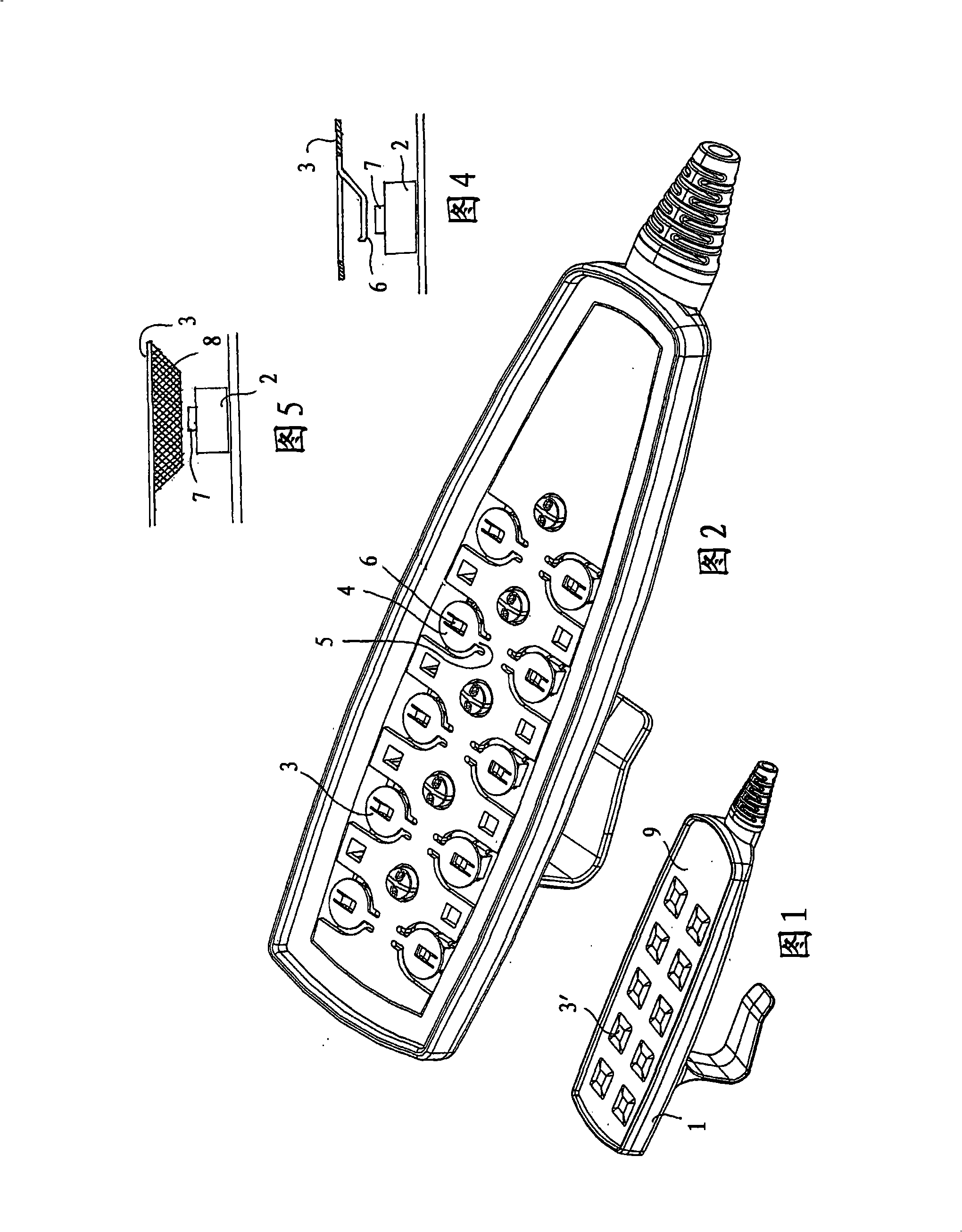
[0015] Embodiments of the present invention relate to hand controls for electrically adjustable nursing and hospital beds that have actuators for raising and lowering the backrest and footrest and are also capable of raising and lowering the entire bed. For this purpose, the hand control is equipped with keys arranged in pairs, one of which is used for ascending and the other for descending.

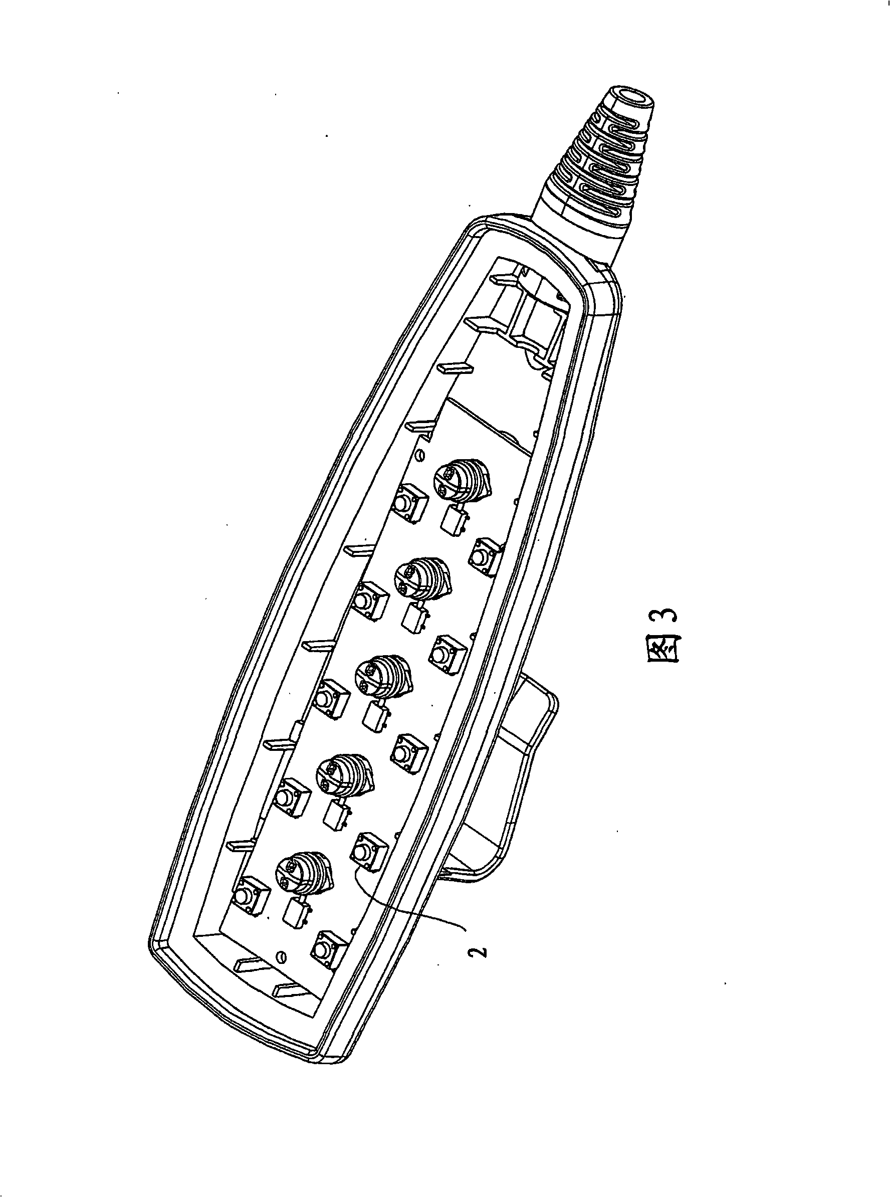
[0016] The hand control comprises a housing 1 in which is mounted a printed circuit with touch switches 2 and above a plate with tongue-like keys 3 in the basic form of circular blocks 4 at the ends of struts 5 . The top surface of the housing is provided with a covering foil 9 with graphics 3' for delimiting the keys and their functions.

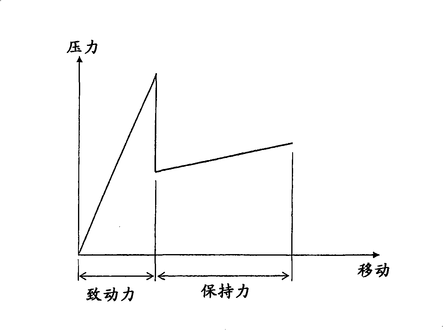
[0017] As can be seen in the detailed view in FIG. 4 , the key 3 is formed with elastic legs 6 . By pressing the key, the elastic leg will immediately press the actuating part 7 of the touch switch, thereby creating an electrical contact. Continued ...


PUM


Abstract

An electric hand control, especially for electrically adjustable hospital and care beds comprising a number of control keys (3) located over a number of switches (2) , and where a spring element (6) is mounted between the control keys (3) and the switches (2) so that an after migration of the control key is obtained, i.e. a migration after the switch is closed. The spring element can for instance be a spring leg (6) or a rubber element. The spring element allows the user to better experience the pressing of the keys and simultaneously the risk of damage as a result of rough operation of the keys is reduced.

Description

technical field [0001] The invention relates to an electric manual control device as stated in the preamble of claim 1 , in particular for electrically adjustable hospital and nursing beds. Background technique [0002] Typically, hand controls for hospital and nursing beds etc. are based on tactile switches mounted on printed circuits in plastic housings. Touch switches are small square-shaped switches with an axially movable actuator on the top surface that when actuated presses metal strips against one another to form a conductive path. The switch is located under the key in the top surface of the hand control, where the key is usually a tongue-shaped member that springs back when the key is released. A thin foil with delimitation of the keys and their functions is mounted over the keys. By pressing the thin foil, the key is pressed inwards and the actuator on the switch is actuated. The movement on the actuator is direct and very modest, with the same or almost the sa...

Claims


Application Information

Patent Timeline
Patent Type & Authority Applications(China)
IPC IPC(8): H01H9/02H01H13/20A61G13/02
CPCA61G7/018H01H13/20H01H9/0214
Inventor H·温特B·卡斯滕森
Owner LINAK AS
Why Eureka
Try Eureka