

Impact tool
A technology of impact tools and tools, applied in the field of impact tools
Active Publication Date: 2008-11-19
MAKITA CORP
View PDF0 Cites 10 Cited by
- Summary
- Abstract
- Description
- Claims
- Application Information
AI Technical Summary
Problems solved by technology
However, the existing electric hammer needs to set a complicated mechanism for reducing vibration, so there is room for improvement in terms of structural rationalization
Method used
View moreImage
Smart ImageViewing Examples

Examples
no. 1 approach
no. 2 approach
Login to View More PUM
 Abstract
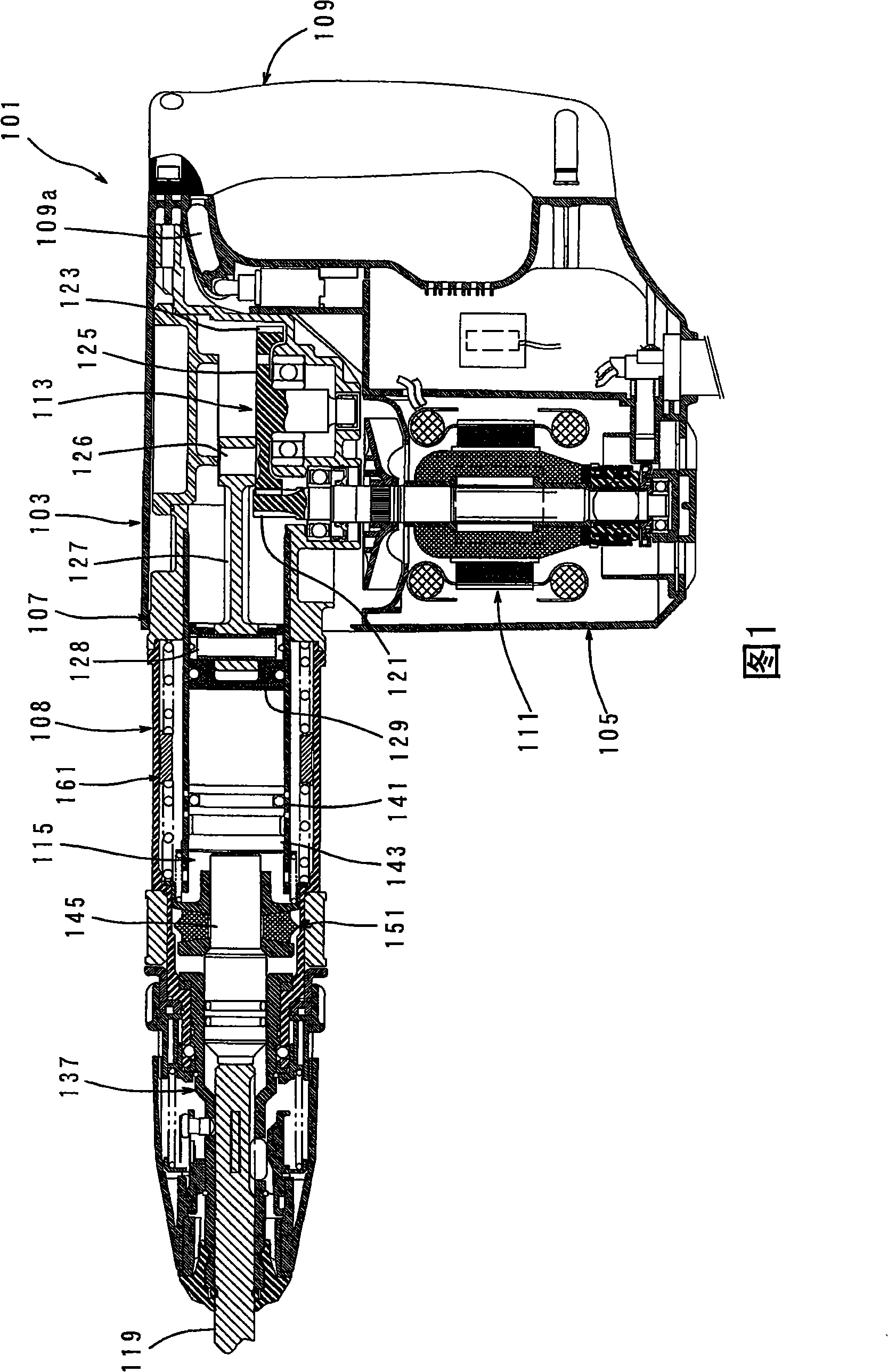
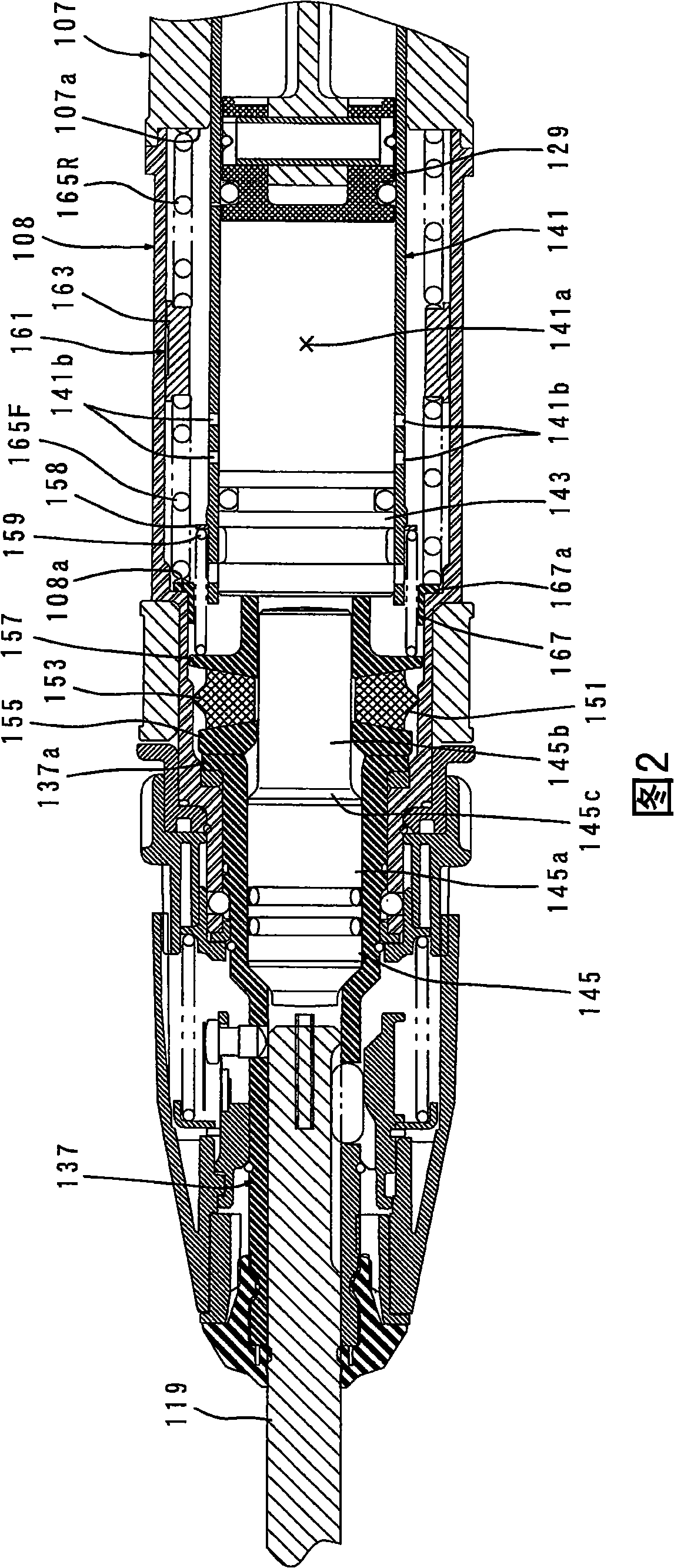
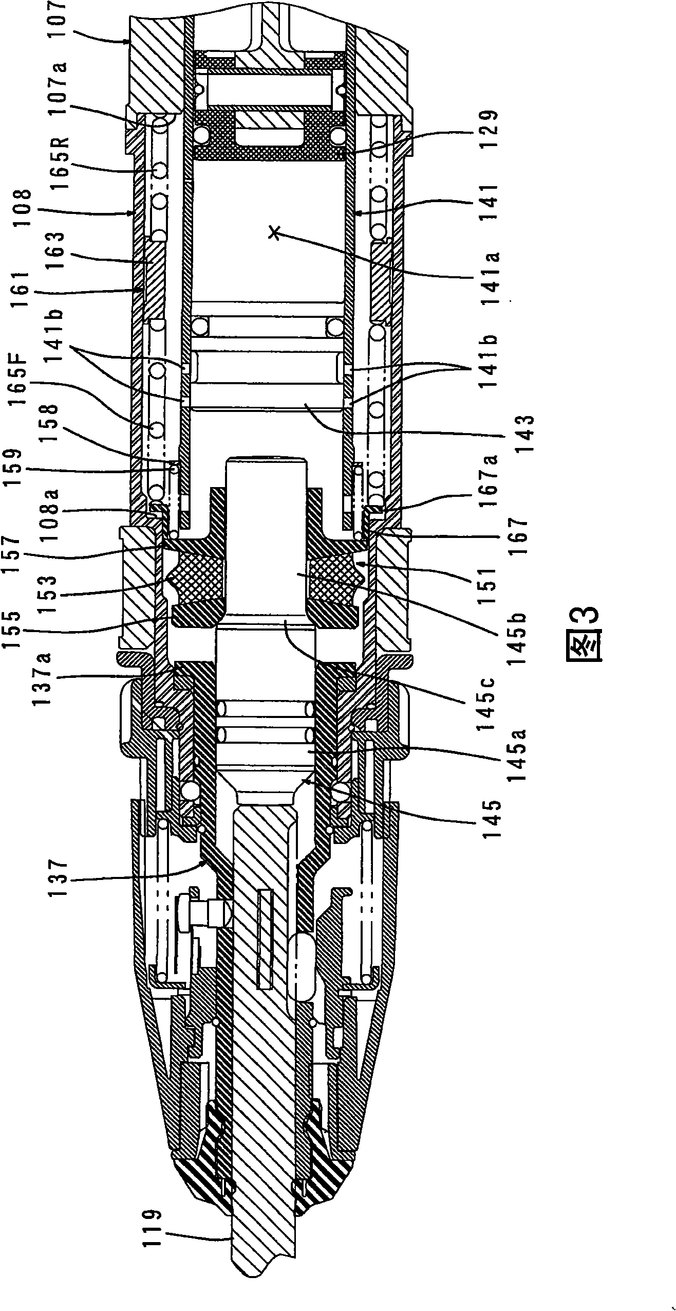
The invention provides an impact tool capable of inhibiting vibration of a tool body generated while hammering process, lessening counterforce to the processed material after impact motions and rationalizing structure of the device. The impact tool includes a tool body (103); a dynamic vibration reducer (161) having a heavy block (163) and elastic components (165F, 165R) and inhibiting vibration while the hammering process; a positioning elastic element which positions the tool body (101) with respect to the processed material prior to the hammering process, so as to, under the positioning state, absorb a counterforce caused by rebound from the processed material and acting on the hammer actuating members (119, 145) when the hammer actuating member (119, 145) perform the hammering process on the processed material. The positioning elastic element includes the elastic elements (165F, 165R) formed as component parts of the dynamic vibration reducer (161).
Description
impact tool technical field The present invention relates to a technique capable of alleviating a reaction force received from a workpiece during the hammering operation in an impact tool for linearly hammering the workpiece. Background technique JP Unexamined Patent Publication No. 52-109673 discloses an electric hammer structure provided with a vibration damping device. In this conventional rotary hammer, an anti-vibration chamber integral with the main body cover (and the motor case) is formed on the lower side of the main body cover in front of the motor case, and a dynamic vibration absorber is housed in the anti-vibration chamber. Therefore, the vibration generated in the direction of the long axis of the hammer bit when the hammer bit is driven is absorbed by the dynamic vibration absorber. However, the conventional electric hammer requires a complicated mechanism for reducing vibration, and thus there is room for improvement in terms of structural rationalization...
Claims
Login to View More Application Information
Patent Timeline
 Patent Type & AuthorityApplications(China)
IPC IPC(8): B25D17/24B25D9/00
Inventor生田洋规龟谷光
OwnerMAKITA CORP