Warp knitting machine

A warp knitting machine and actuator technology, applied in the field of warp knitting machines, can solve problems such as the quality reduction of knitted fabrics

Active Publication Date: 2013-03-13
KARL MAYER STOLL R&D GMBH
View PDF8 Cites 13 Cited by
  • Summary
  • Abstract
  • Description
  • Claims
  • Application Information

AI Technical Summary

Problems solved by technology

Already small misadjustments lead t

Method used


Image

  • Warp knitting machine
  • Warp knitting machine

Examples


Embodiment Construction

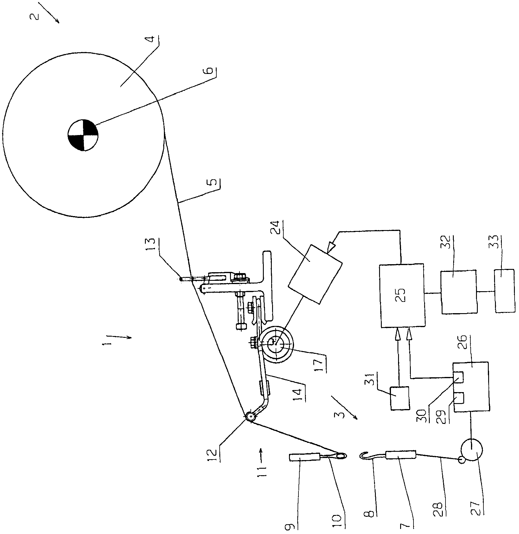
[0025] figure 1 A warp knitting machine 1 with a thread feeding area 2 and a knitting area 3 is shown very schematically. In this case, a warp beam 4 is arranged in the thread feeding area 2 , which provides the yarn sheets. The yarn sheet has a plurality of threads 5 arranged side by side, one of which can be seen in the figure. Other lines follow it perpendicular to the drawing plane.

[0026] The warp beam 4 is driven by the drive 6 in such a way that the wire 5 is fed at a constant speed.

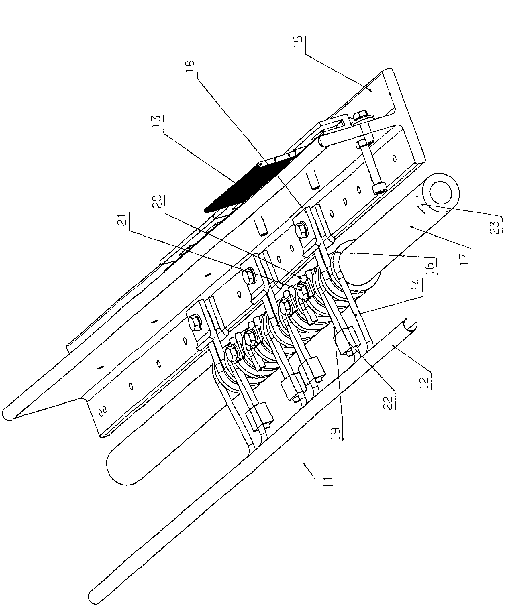
[0027] The knitting area 3 shown here in a very simplified manner has a needle bar 7 on which a plurality of knitting needles 8 are arranged. The knitting needles 8 are arranged one after the other perpendicular to the drawing plane, so that only one knitting needle 8 is visible. Furthermore, the knitting area 3 has a bar 9 on which a plurality of eye needles 10 are arranged. The other eye pins are located perpendicular to the drawing plane. Each thread 5 is guided through an eye ...


PUM


Abstract

The knitting machine (1) has a yarn feeding portion (2), an active region (3), and a thread tension compensating device (11) between the yarn feeding portion and the active region. The quality of knitted fabric is reduced to the minimum through a simple method. Therefore, the thread tension compensating device (11) can be actuated from the outside through a control device (17, 24) with which a natural frequency of the tension compensating device is varied.

Description

technical field [0001] The invention relates to a warp knitting machine with a thread feeding area, a knitting area and a thread stress equalization device between the thread feeding area and the knitting area. Background technique [0002] In the production of knitted fabrics, warp threads are often fed from the feeder region at a constant speed. For this purpose, the thread feeding area has, for example, a warp beam, which is driven in such a way that the speed of the supplied thread is constant. However, during the knitting process itself, ie during the actual loop formation, the thread consumption is not constant, but fluctuates around a mean value which corresponds to a constant speed. Nevertheless, in order to achieve a good mesh structure and good loop formation, a thread stress equalizer is arranged between the thread feeding area and the knitting area. Different wire consumptions are balanced during looping with this wire stress balancing device. The line stress ...

Claims


Application Information

Patent Timeline
IPC IPC(8): D04B27/00D04B27/10
CPCD04B27/14
Inventor K・B・布兰德尔
Owner KARL MAYER STOLL R&D GMBH
Why Eureka
Try Eureka