Air conditioner

A technology of air conditioning and air outlet, applied in air conditioning system, space heating and ventilation, space heating and ventilation details, etc. It can solve the problems of vibration and air susceptible to vibration, and achieve the effect of stable guidance.

Inactive Publication Date: 2008-11-19
LG ELECTRONICS INC
View PDF0 Cites 4 Cited by
  • Summary
  • Abstract
  • Description
  • Claims
  • Application Information

AI Technical Summary

Problems solved by technology

[0005] However, in the air conditioner according to the related art, since the pivot shafts of the vanes are directly connected to the rotation shafts of the vane motors so as to rotate together with the rotation shafts of the vane motors, the parts connected around the pivot shafts are easily vibrated during the rotation of the vanes or may be caused by The blown air vibrates

Method used


Image

  • Air conditioner
  • Air conditioner
  • Air conditioner

Examples


Embodiment Construction

[0021] Reference will now be made in detail to embodiments of the invention, examples of which are illustrated in the accompanying drawings.

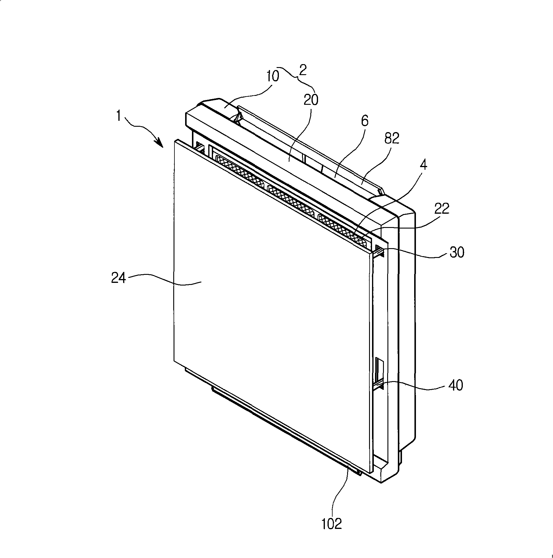
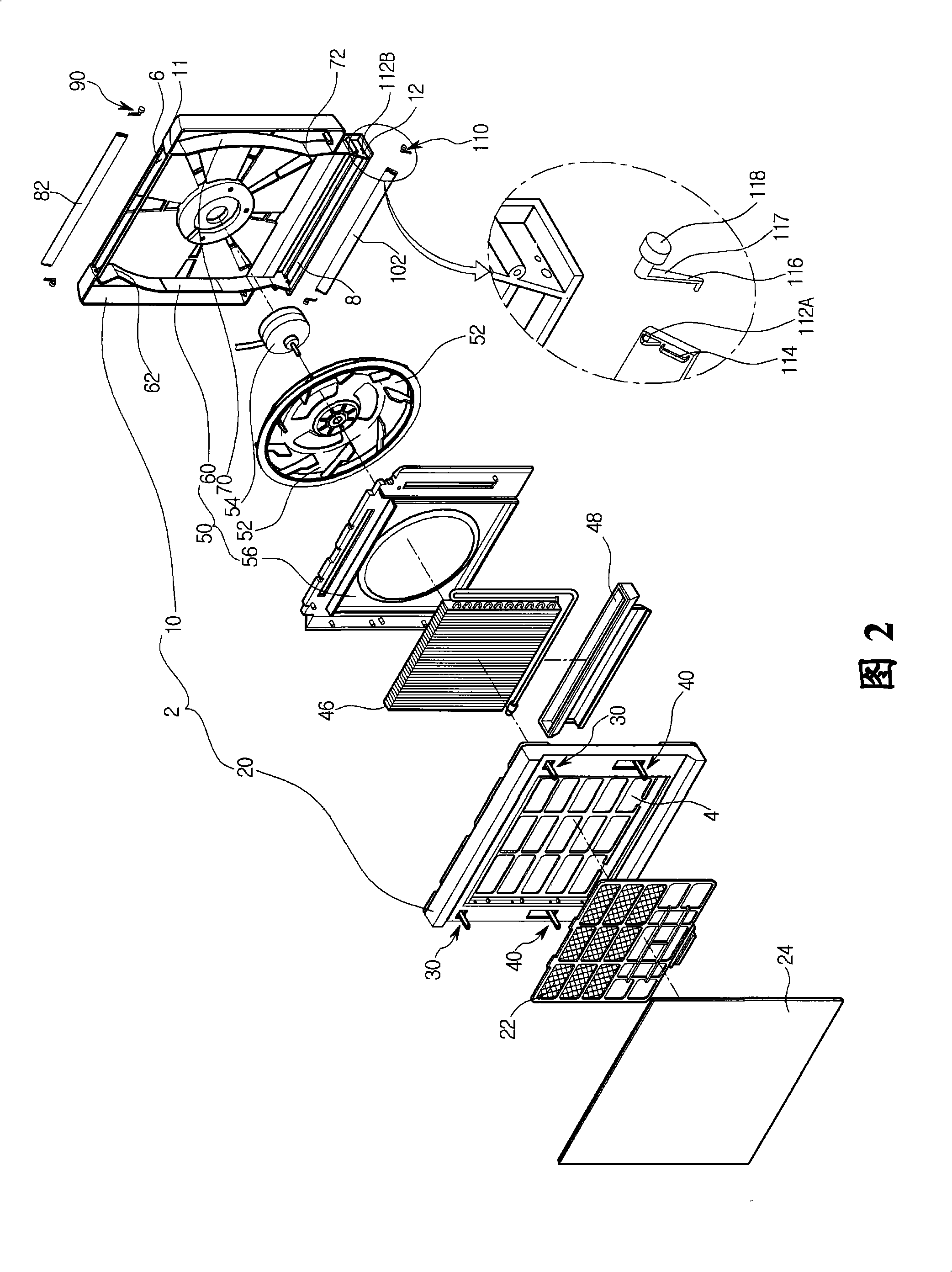
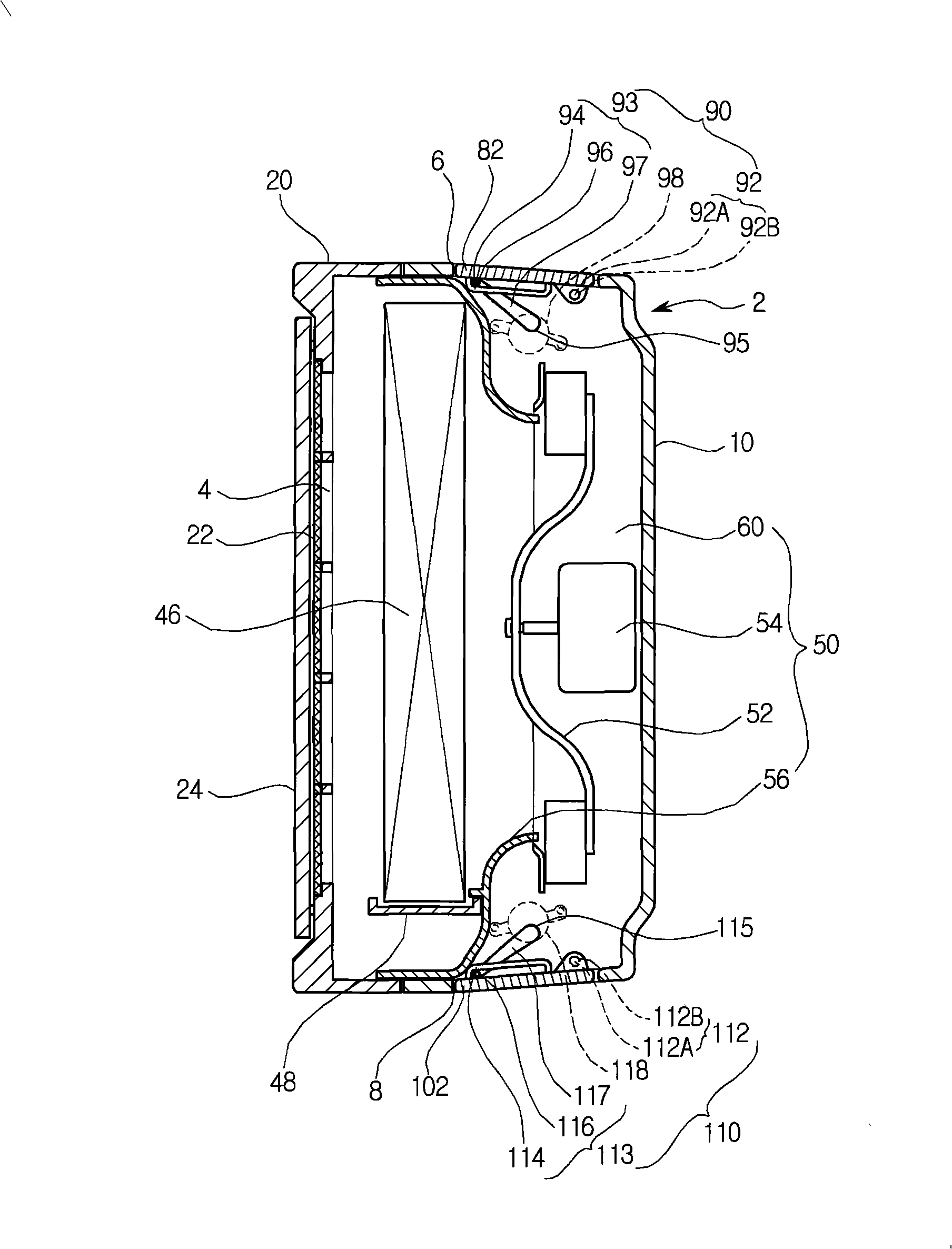
[0022] figure 1 is a perspective view of the air conditioner according to the present embodiment, and FIG. 2 is an exploded perspective view of the air conditioner according to the present embodiment, image 3 is a cross-sectional view of the air conditioner when it is not working, Figure 4 is a cross-sectional view of the air conditioner in upper discharge mode, and Figure 5 is a cross-sectional view of the air conditioner in the lower discharge mode.

[0023] Figure 1 to Figure 5 An indoor unit of a wall type air conditioner is shown, and the following description will be limited to the indoor unit of the air conditioner.

[0024] refer to Figure 1 to Figure 5 , The indoor unit 1 of the air conditioner according to the present embodiment includes a main body 2 constituting the exterior of the indoor unit 1 .

[0025] An air ...


PUM


Abstract

The invention provides an air conditioner which comprises a main body, a blade and a blade driving unit. The main body restricts an air inlet and an air outlet. The blade is connected to the main body through a hinge by rotatable manner for opening and closing the air outlet. The blade driving unit is connected to the part of the blade separated from the hinge for driving the blade.

Description

technical field [0001] The invention relates to an air conditioner. Background technique [0002] Generally, an air conditioner is a device that cools or warms an indoor environment using a compressor, condenser, expander, and evaporator. [0003] Such an air conditioner includes an indoor unit installed indoors and an outdoor unit installed outdoors. Alternatively, the indoor unit and the outdoor unit may be integrated according to the type of the air conditioner. [0004] An indoor unit includes a body that constitutes its exterior. An air inlet and an air outlet are defined in the body. In addition, vanes are provided at the air outlet to guide the direction of the airflow discharged from the air outlet. The vanes are driven by vane motors. Here, one side of the vane is connected to the rotation shaft of the vane motor so that the vane rotates around the center of the rotation shaft of the vane motor to open and close the air outlet. [0005] However, in the air con...

Claims


Application Information

Patent Timeline
Patent Type & Authority Applications(China)
IPC IPC(8): F24F1/00
CPCF24F1/0011F24F13/1486F24F2013/1433
Inventor 阳承勋
Owner LG ELECTRONICS INC
Why Eureka
Try Eureka