Medium transportation apparatus and image forming apparatus

a technology of transportation apparatus and medium, applied in the direction of transportation and packaging, electrographic process, instruments, etc., can solve the problems of difficult stably guiding the sheet, excessive size of the switching guide in the longitudinal direction, etc., and achieve the effect of stably guiding the medium

Active Publication Date: 2016-05-03
OKI DATA CORP
View PDF9 Cites 2 Cited by
  • Summary
  • Abstract
  • Description
  • Claims
  • Application Information

AI Technical Summary

Benefits of technology

[0012]According to the aspect of the present invention, when the switching guide is situated at the first guiding position, the first engaging portion engages with the second engaging portion. Accordingly, it is possible to restrict the first engaging portion from being moved, so that the switching guide is restricted to be moved. As a result, even though the switching guide is curved or deformed, it is possible to stably guide the medium when the switching guide switches a guiding route.

Problems solved by technology

In the conventional image forming apparatus disclosed in Patent Reference, the switching guide tends to have an excessive size in a longitudinal direction thereof.
When the switching guide is deformed, it is difficult to stably guide the sheet when the switching guide switches the guiding route.

Method used


Image

  • Medium transportation apparatus and image forming apparatus
  • Medium transportation apparatus and image forming apparatus
  • Medium transportation apparatus and image forming apparatus

Examples


first embodiment

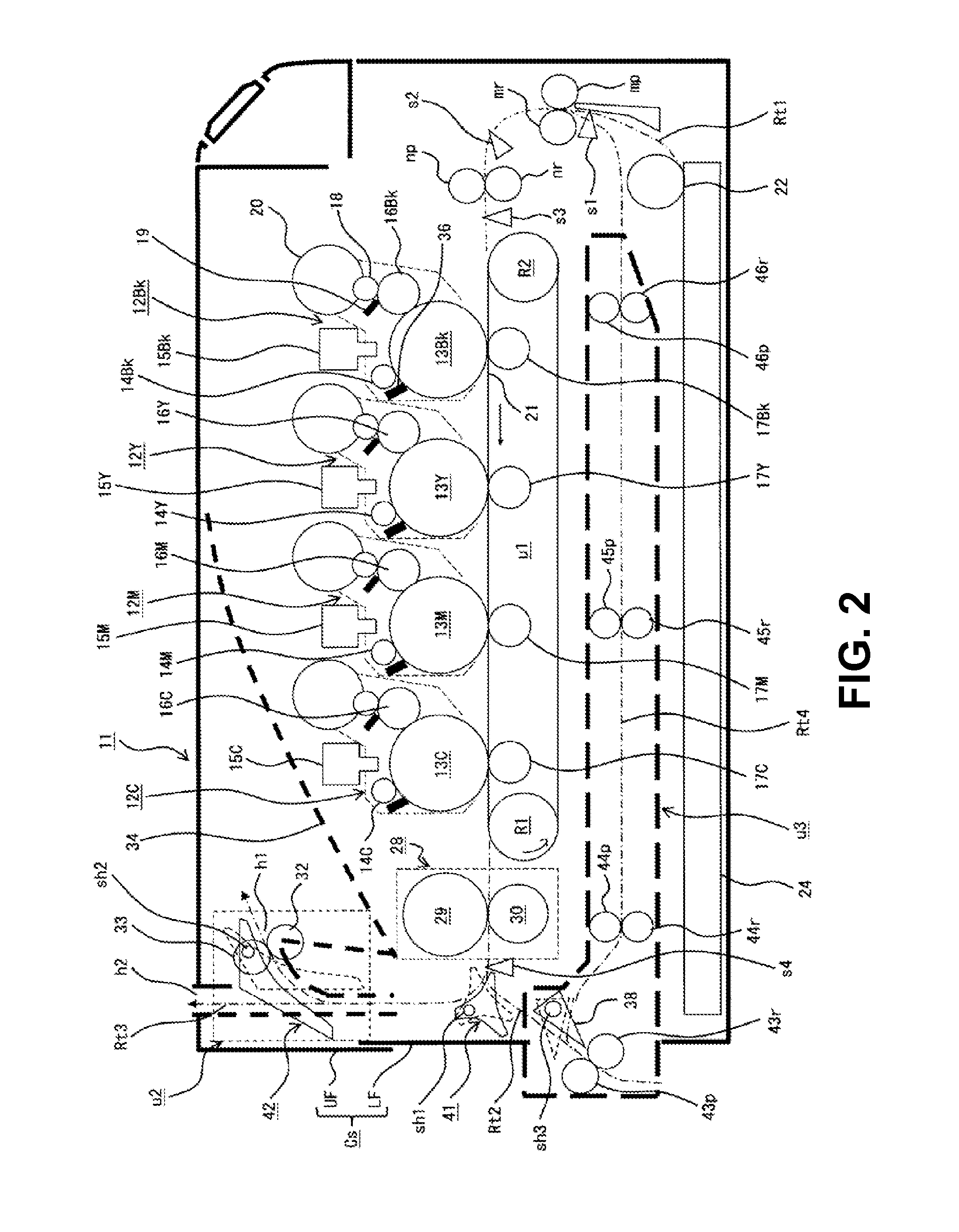
[0035]A first embodiment of the present invention will be explained. FIG. 2 is a schematic sectional view showing a configuration of a printer 11 according to the first embodiment of the present invention.

[0036]As shown in FIG. 2, the printer 11 includes a casing Cs formed of an upper frame UF and a lower frame LF. In the casing Cs, there are disposed four image forming units 12Bk, 12Y, 12M, and 12C as an image forming portion arranged from an upstream side toward a downstream side in a transportation direction of a sheet (not shown) as a medium. The image forming units 12Bk, 12Y, 12M, and 12C are configured to form toner images as developer images in colors of black, yellow, magenta, and yellow, respectively. It should be noted that an OHP (Over Head Projector) sheet, an envelope, a copy sheet, a special sheet, and the like are used as the medium.

[0037]In the first embodiment, the image forming units 12Bk, 12Y, 12M, and 12C include photosensitive drums 13Bk, 13Y, 13M, and 13C as im...

second embodiment

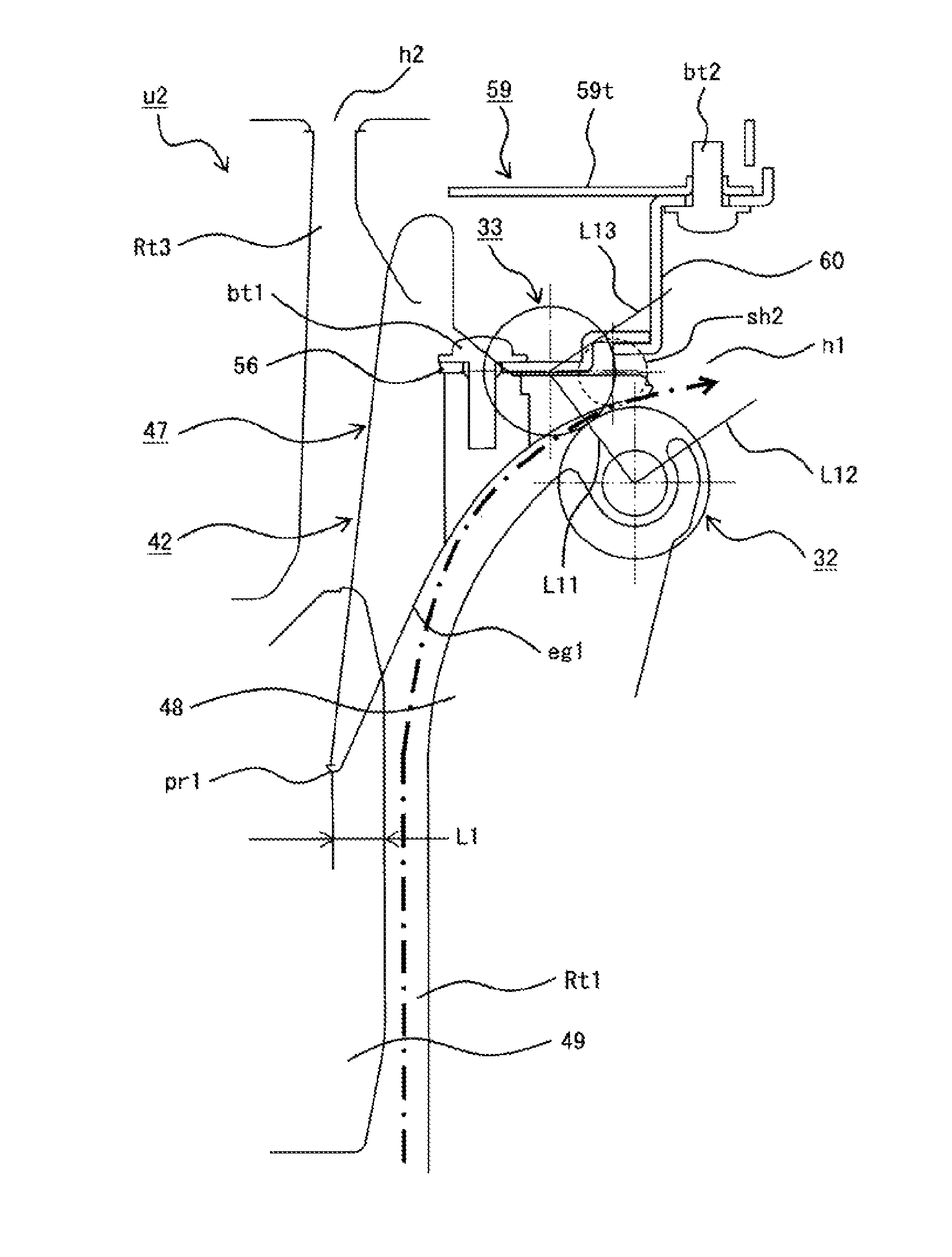
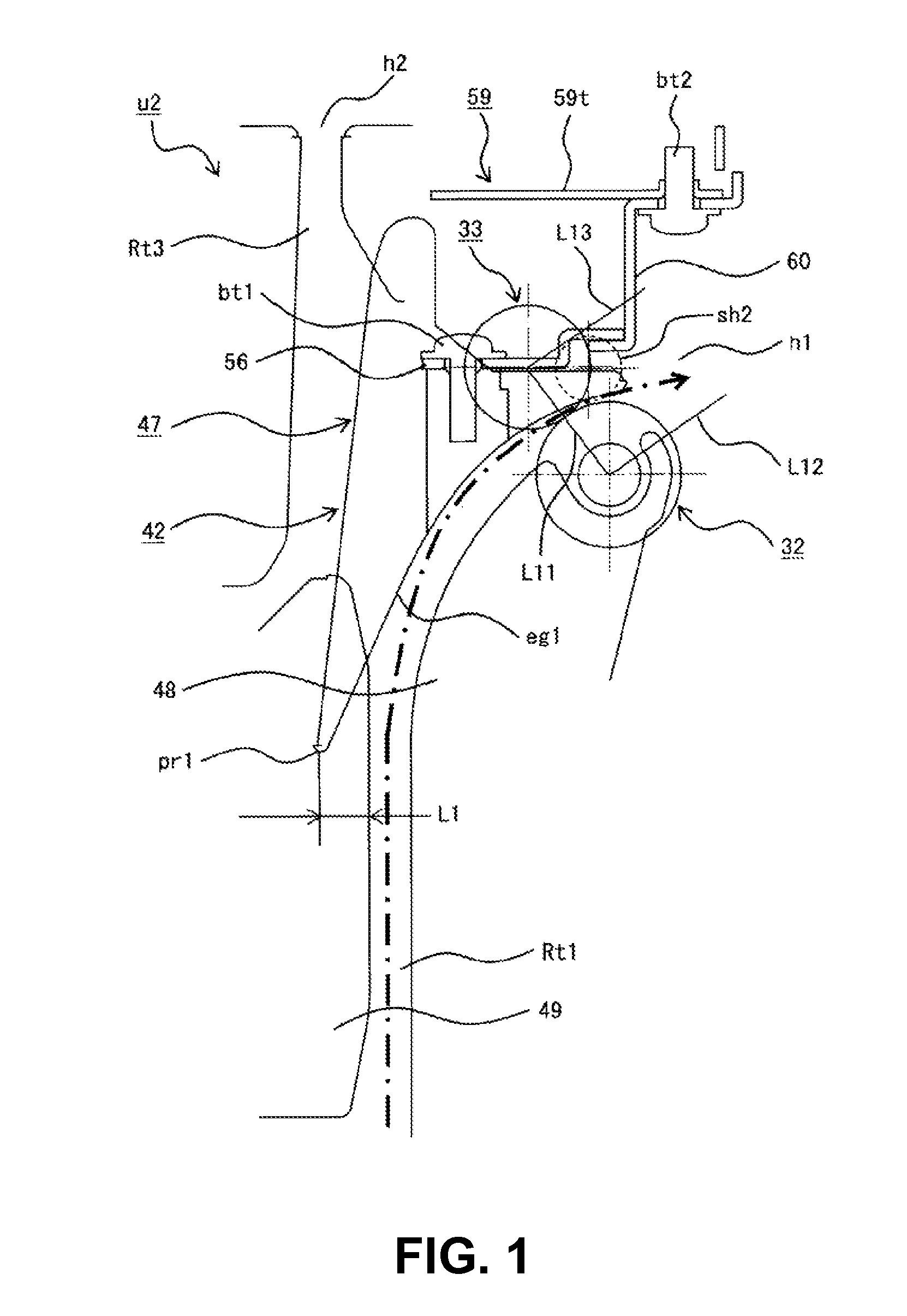
[0138]A second embodiment of the present invention will be explained next. FIG. 21 is a schematic sectional view showing an operation of the medium discharging unit u2 of the printer 11 when the discharging route is set according to a second embodiment of the present invention.

[0139]In the first embodiment, when the color image is formed on the sheet, toner is heated and permeates into the sheet in the fixing device 28. Accordingly, when the toner images in colors are fixed to the sheet, the sheet may be curled in the transportation direction thereof.

[0140]To this end, in the second embodiment, as shown in FIG. 21, the discharging rib portions eg1 are formed in a specific shape such that the pointy end portions pr1 of the switching ribs 47 and the opposite end portions pr2 at the opposite side are shifted from the nip portion Np of the discharging roller 32 and the discharging roller 33 by a distance L3 toward the discharging route ribs 48 when the second discharging guide 42 is sit...


PUM

PropertyMeasurementUnit
angleaaaaaaaaaa
angleaaaaaaaaaa
voltageaaaaaaaaaa

Abstract

A medium transportation apparatus includes a fixed member fixed to an apparatus main body, and a switching guide for guiding a medium. The switching guide is disposed to be freely rotatable relative to the apparatus main body, and to be freely switched between a first guiding position and a second guiding position. The switching guide includes a medium guiding portion and a first engaging portion integrally formed with the medium guiding portion. The fixed member includes a second engaging portion for engaging with the first engaging portion. When the switching guide is situated at the first guiding position, the first engaging portion engages with the second engaging portion.

Description

BACKGROUND OF THE INVENTION AND RELATED ART STATEMENT[0001]The present invention relates to a medium transportation apparatus and an image forming apparatus.[0002]In a conventional image forming apparatus using an electro-photography method such as a printer, a copier, a facsimile, a multi function product, and the like, there are provided a photosensitive drum; a charging roller for uniformly charging a surface of the photosensitive drum; and an LED (Light Emitting Diode) head for forming a static latent image on the surface of the photosensitive drum thus charged. The conventional image forming apparatus further includes a developing roller for developing the static latent image to form a toner image; a transfer roller for transferring the toner image to a sheet as a medium; and a fixing device for fixing the toner image to the sheet.[0003]Patent Reference has disclosed a printer as such the conventional image forming apparatus. The printer disclosed in Patent Reference is configu...

Claims


Application Information

Patent Timeline
Patent Type & Authority Patents(United States)
IPC IPC(8): G03G15/00B65H29/58
CPCG03G15/6529B65H29/58G03G15/6552G03G2215/00675G03G2215/00679B65H29/14B65H29/70B65H85/00B65H2301/33312B65H2301/5122B65H2402/10B65H2402/31B65H2404/143B65H2404/632B65H2555/13B65H5/062B65H2404/611
Inventor HARUYAMA, MASAHIRO
Owner OKI DATA CORP
Why Eureka
Try Eureka