
Shock resistance axial seal device for screw shaft of ship

An end-face sealing and impact-resistant technology, applied in the direction of engine sealing, engine components, mechanical equipment, etc., can solve the problems of inability to automatically compensate, lack of maintainability, unstable wire springs, etc., and achieve stable performance of friction pair water sealing Reliable, good seawater corrosion resistance, and the effect of improving safety and comfort

Active Publication Date: 2011-07-20
WUXI HONGYUAN DEVFLEX
View PDF0 Cites 0 Cited by
  • Summary
  • Abstract
  • Description
  • Claims
  • Application Information

AI Technical Summary

Problems solved by technology

After this structure is used for a period of time, the wear that cannot be automatically compensated due to relative sliding will gradually lead to an increase in the fit clearance and an increase in water leakage.
After a certain amount of clearance is exceeded, the sealing device will lose its function, and the entire sealing device must be replaced. The maintenance cycle is long and the cost is high. Axle jamming occurs, resulting in downtime and suspension, sometimes the consequences are unimaginable
Although the existing end face seal device with wire spring structure has the ability to compensate for wear in the axial direction, due to the instability of the wire spring in the lateral direction, the possible axial deviation during installation or the radial direction caused by vibration and impact The deformation compensation ability is very small, and it does not have maintainability under sailing conditions; in addition, the existing various stern shaft sealing devices cannot effectively isolate the impact of shafting vibration on the hull

Method used


Image

  • Shock resistance axial seal device for screw shaft of ship
  • Shock resistance axial seal device for screw shaft of ship
  • Shock resistance axial seal device for screw shaft of ship

Examples


Embodiment Construction

[0025] Below the present invention will be further described in conjunction with the embodiment in the accompanying drawing:

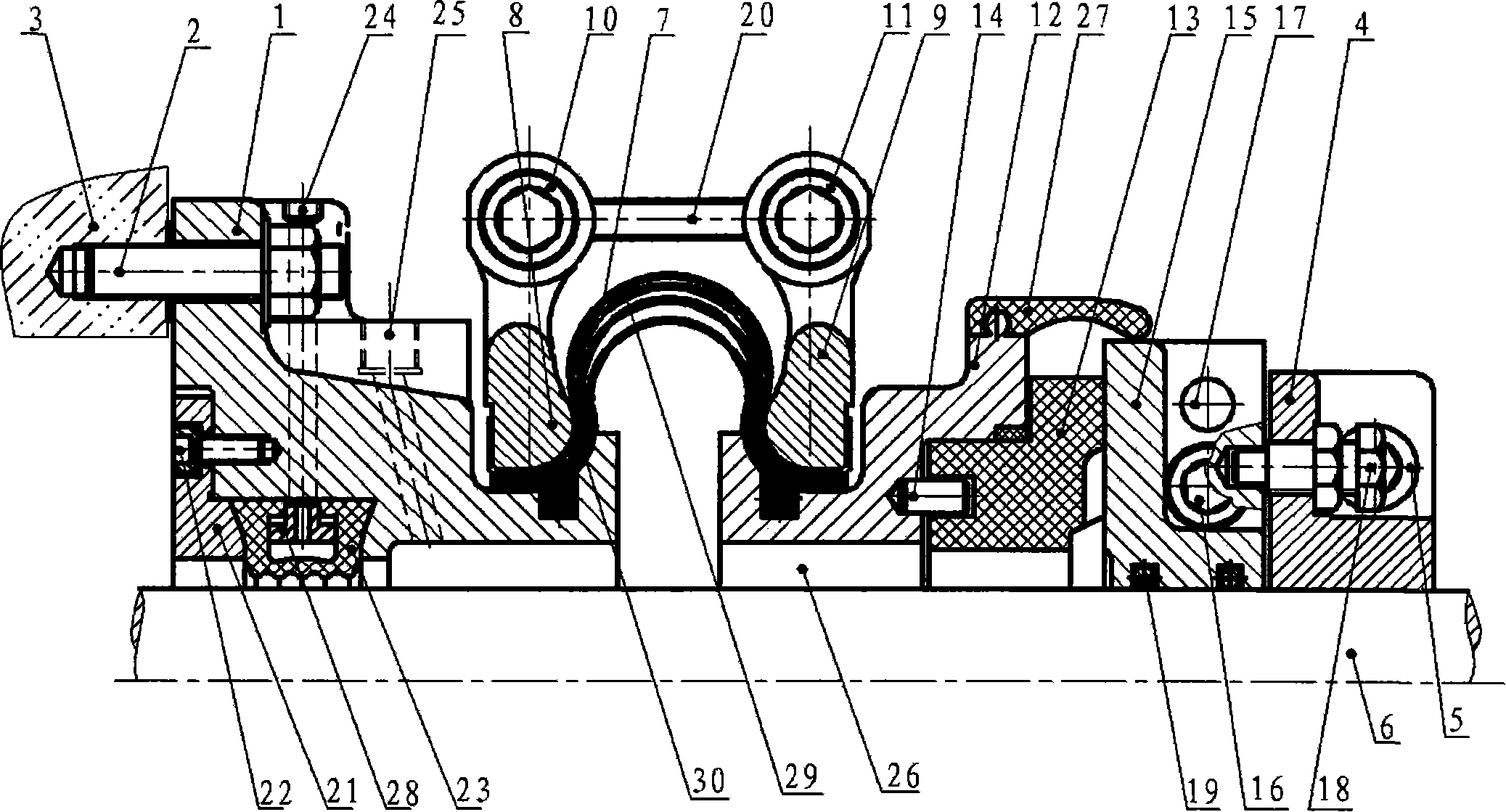
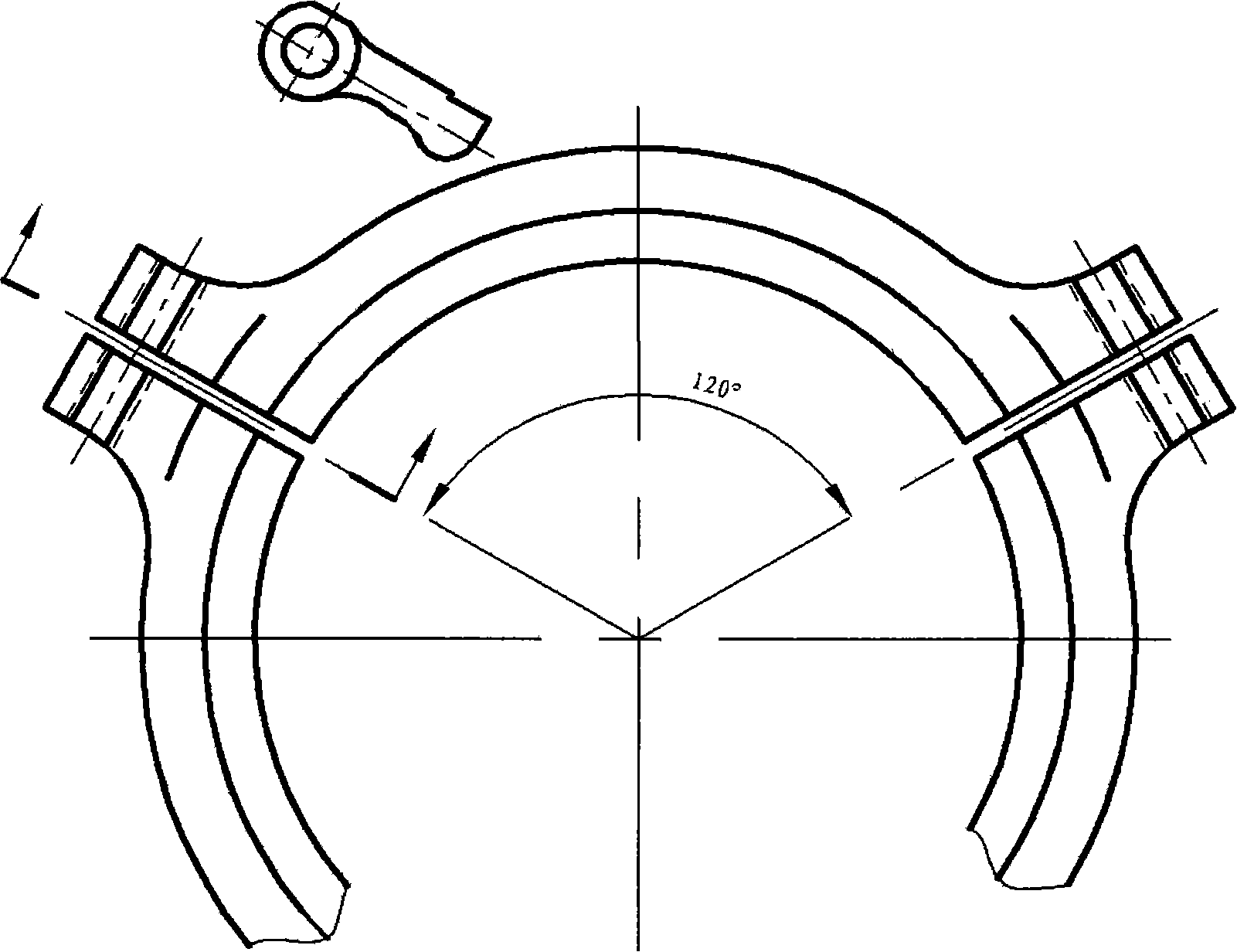
[0026] as attached figure 1 As shown, the present invention consists of a mounting base 1, a transmission snap ring 4, an Ω-shaped elastic compensator 7, main collars 8, 9, lock nuts 10, 11, a seal ring bracket 12, a seal ring 13, a support ring 15, Cone pin 17, bolt 18, o-shaped ring 19, adjusting screw rod 20, pressure ring 21, inflatable seal 23, splash guard 27 and several seals and connectors are assembled. The installation base 1 is fixed on the hull stern tube seat 3 with bolts 2 . The transmission snap ring 4 is formed by two halves of the annular body, and is fastened on the stern shaft 6 by bolts 5 and taper pins. The left and right ends of the Ω-shaped elastic compensator 7 are firmly pressed on the installation base 1 and the sealing ring bracket 12 by the main collars 8 and 9 through the locking bolts 10 and 11 respectively. Each main c...


PUM


Abstract

The invention provides an anti-impact type end surface seal device of a ship tail-shaft used for a water seal of a ship tail-shaft. An axial elastic restoring force generated by a layered Omega-shaped elastic compensating body under a pre-compressing state is utilized to lead a seal ring to be closely stuck with the end surface of a bearing ring for forming an automatic abrasion complementing type water seal friction pair; simultaneously, the coaxial direction and the radial direction of the Omega-shaped elastic compensating body are provided with enough elastic deformation characteristics which can automatically complement the axes excursion or bending and deformation of the tail-shaft during mounting and running as well as reduce the transferring of vibration and impact to the body of the ship. An enough clearance is arranged at the relative moving part between the end surface seal device and the ship tail-shaft; the tail-shaft runs with no abrasion; a charging seal closely holds the tail-shaft under an air charging state to form a radial water seal, which is convenient for over-water maintenance and emergency sailing of the ship. The endurance rate of the ship is high; the capacity of coping with severe environment is strong.

Description

technical field [0001] The invention provides a ship stern shaft impact-resistant end face sealing device, which is used for water sealing of stern tubes of various ship propulsion shafts, maintains the normal operation of the stern shaft in a non-wearing state, and reduces the vibration and impact response of the stern tube and hull. [0002] The invention belongs to the technology of ship propulsion shafting stern shaft seal and its operation reliability, and aims at improving the water sealing performance, cruising rate and service life of the ship stern shaft sealing device and improving the emergency capability of the ship in the harsh environment on water. Background technique [0003] The ship stern shaft sealing device and the stern shaft are in a long-term relative rotation and watertight state. The relative movement surface of the stern shaft and the sealing device will gradually increase the water leakage due to wear and tear, which will affect the normal navigatio...

Claims


Application Information

Patent Timeline
Patent Type & Authority Patents(China)
IPC IPC(8): F16J15/48
Inventor 胡年丰胡倩平胡雪凡
Owner WUXI HONGYUAN DEVFLEX
Learn More