Image checking device and image checking mehtod

A technology for inspection devices and graphics, which can be used in measurement devices, optical devices, and material analysis by optical means, and can solve problems that have not yet been established.

Inactive Publication Date: 2008-11-26
USHIO DENKI KK
View PDF2 Cites 12 Cited by
  • Summary
  • Abstract
  • Description
  • Claims
  • Application Information

AI Technical Summary

Problems solved by technology

In order to inspect patterns in a short time, it is necessary to measure the line width of patterns while distinguishing and d...

Method used


Image

  • Image checking device and image checking mehtod
  • Image checking device and image checking mehtod
  • Image checking device and image checking mehtod

Examples


Embodiment Construction

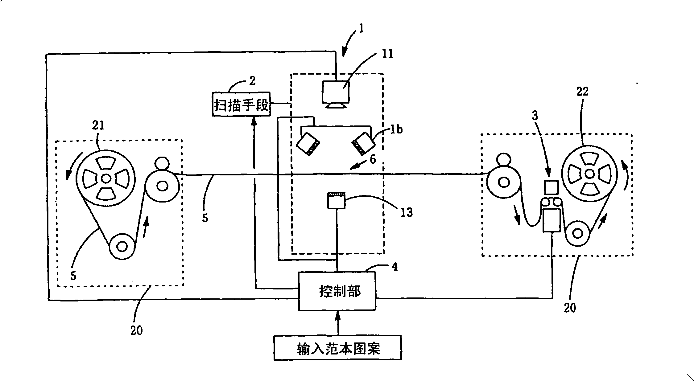
[0056] figure 1 is a block diagram of a wiring pattern inspection device according to an embodiment of the present invention. In addition, although the following embodiments are described for the case where the substrate is a thin-film workpiece such as TAB tape or COF, the present invention can also be applied to pattern inspection of other substrates.

[0057] The pattern inspection device of the present embodiment, as shown in the figure, is equipped with: the tape conveying mechanism 20 that is constituted by sending out reel 21 or take-up reel 22 etc. that TAB tape 5 is conveyed; The inspection unit 1 that irradiates the transmitted illumination light and reflected illumination light on the TAB tape 5 and takes an image of the inspection pattern 6, the scanning unit 2 that makes the inspection unit 1 scan the inspection pattern 6 on the TAB tape 5, and attaches to the unqualified pattern. Marking part 3 of the mark.

[0058] In the marking part 3, the pattern judged to...


PUM


Abstract

The invention provides a detecting device of wiring figures and a method thereof, which can differentiate dents and protuberances generated on the surface of the figures, and can a measure linewidth when detecting out the dents. As means to solve the problems, from one side equipped with figures of TAB belts, luminous light is irradiated in a slantly ripping way for the detected area through a reflecting luminous unit (12), meanwhile from the opposite side of one side formed with figures, the luminous light is irradiated through a transmission luminous unit (13), and figures are shot through a shooting unit (11). If dents are present on the surface of the figures, the reflected light from the reflecting luminous unit (12) is ripped into the shooting unit (11), and the part is shot as brightness. Also, through the luminous light from the transmission luminous unit (13), the part formed with figures are shot as grey, while the part not formed with figures are shot as brightness. Therefore, through using the reflected illumination and the transmission illumination to shoot, the linewidth can be measured when detecting out the dents.

Description

field of invention [0001] The present invention relates to a pattern inspection device and a pattern inspection method, in particular to detecting whether there are pits (holes) on the surface of a wiring pattern formed on a substrate such as a TAB (Tape Automated Bonding) tape, A pattern inspection device and a pattern inspection method capable of measuring the line width of a pattern. Background technique [0002] In inspection of wiring patterns, for example, Patent Document 1 or Patent Document 2 proposes methods and devices for distinguishing dust (foreign matter) adhering to the surface or back of a substrate from defects in wiring patterns and preventing erroneous detection. [0003] In the above-mentioned gazette, it is described that a reflected illumination image obtained by receiving an image reflected by illumination light from a substrate on which a wiring pattern is formed is compared with a transmitted illumination image obtained by receiving an image transmit...

Claims


Application Information

Patent Timeline
IPC IPC(8): G01N21/956G01B11/02
CPCG01N21/9501G01N21/95607H01L22/12
Inventor 野本宪太郎松田僚三林宏树
Owner USHIO DENKI KK
Why Eureka
Try Eureka