Charging device, motor-driven vehicle, and charging system

A technology for charging devices and electric vehicles, which is applied in the direction of electric devices, electric vehicles, circuit devices, etc., can solve the problems of inability to ensure charging power and increase user burden, and achieve the effect of reliable charging and guaranteed cooling state

Inactive Publication Date: 2008-11-26
TOYOTA JIDOSHA KK
View PDF1 Cites 11 Cited by
  • Summary
  • Abstract
  • Description
  • Claims
  • Application Information

AI Technical Summary

Problems solved by technology

Therefore, this may lead to a situation where the input commercial electric power may be consumed by the driving of the cooling device and the loss generated in the voltage conversion, and the charging power for the power storage device cannot be secured.
[0007] On the other hand, increasing the amount of power set under the contract with the power company imposes a burden on the user
Even in the case of increasing the amount of power set under the contract, if the power storage device is enlarged in size in the future and the cooling device has a correspondingly higher cooling capacity, it cannot be ensured that the charging power for the power storage device can be reliably guaranteed

Method used


Image

  • Charging device, motor-driven vehicle, and charging system
  • Charging device, motor-driven vehicle, and charging system
  • Charging device, motor-driven vehicle, and charging system

Examples


no. 1 example

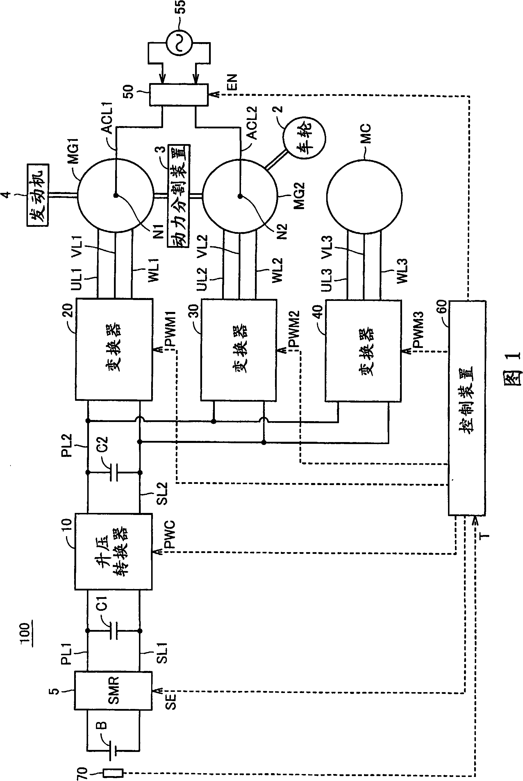
[0044] FIG. 1 is an overall block diagram of a hybrid vehicle shown as an example of an electric vehicle according to a first embodiment of the present invention. Referring to FIG. 1 , a hybrid vehicle 100 includes an engine 4 , motor generators MG1 and MG2 , a power split device 3 , and wheels 2 . Hybrid vehicle 100 further includes power storage device B, system main relay 5, boost converter 10, inverters 20 and 30, input port 50, control device 60, capacitors C1 and C2, power supply lines PL1 and PL2, and ground line SL1. and SL2, U-phase lines UL1 and UL2, V-phase lines VL1 and VL2, and W-phase lines WL1 and WL2. Hybrid vehicle 100 also includes inverter 40 , U-phase line UL3 , V-phase line VL3 , W-phase line WL3 , compressor MC for an air conditioner, and temperature sensor 70 .

[0045] Power split device 3 is connected to engine 4 and motor generators MG1 and MG2 to distribute power therebetween. For example, a planetary gear mechanism having three rotation shafts of ...

no. 2 example

[0083] In the second embodiment, the configuration of a charging system capable of charging a plurality of electric vehicles is shown.

[0084] Image 6 It is an overall block diagram schematically showing a charging system according to a second embodiment of the present invention. although Image 6 A case where two electric vehicles are charged as an illustrative example is shown, but more than two electric vehicles may also be charged.

[0085] refer to Image 6 , the charging system 200 includes the hybrid vehicles 100A and 100B, the charging station 80 , and the commercial power supply 55 . Each hybrid vehicle 100A, 100B is connected to the charging station 80 via the input port 50A, and receives commercial power supplied from the commercial power supply 55 from the charging station 80 via the power input lines ACL1 and ACL2. In addition, hybrid vehicles 100A and 100B each calculate the SOC of the power storage device mounted thereon, and output the calculated SOC to c...


PUM


Abstract

During charge control of an accumulation device (B) from a commercial power source (55), charging and cooling of the accumulation device (B) are performed at time division. That is, when the temperature of the accumulation device (B) is increased, a control device (60) turns OFF a system main relay (5), stops a boosting converter (10), and drives an inverter (40) to operate a compressor (MC) for an air conditioner. When the accumulation device (B) is cooled down, the control device (60) again turns ON the system main relay (5), drives the boosting converter (10), and stops the inverter (40).

Description

technical field [0001] The present invention relates to a charging device, an electric vehicle and a charging system, in particular to a charging method for a charging device installed on an electric vehicle and capable of charging an electric storage device from a commercial power source outside the vehicle. Background technique [0002] Japanese Patent Laid-Open No. 5-276677 discloses a charging device that charges a power storage device mounted on an electric vehicle such as an electric vehicle or a hybrid vehicle by using an external power source. The charging device includes a cooling device for cooling the power storage device and a drive circuit for driving the cooling device using charging power from the charger. [0003] In the charging device, when charging power is supplied from the charger to the power storage device, part of the charging power is also supplied to the cooling device, so the cooling device cools the power storage device while the power storage dev...

Claims


Application Information

Patent Timeline
Patent Type & Authority Applications(China)
IPC IPC(8): B60L11/18H01M10/44H02J7/00H02J7/02
CPCB60K6/365Y02T10/642H02J7/0027Y02T10/7005B60L11/187Y02T90/127B60L11/1874B60L15/007B60L11/1816B60K1/02B60L11/1824B60L2220/14Y02T10/641Y02T10/7077B60W2510/246B60L11/14Y02T10/7088B60K2001/005B60K6/445Y02T90/121H01M10/502Y02T10/7022Y02E60/12Y02T10/7055H01M10/5004Y02T10/6239H01M10/5016H02P2201/09Y02T90/14B60L11/1872H01M10/44B60L2220/54Y02T10/7225B60L2210/14Y02T10/705B60L11/123Y02T10/6217Y02T10/6269B60L11/1814Y02T10/92H01M10/625H01M10/63H01M10/613Y02T10/7072B60L53/14B60L50/61B60L50/16B60L53/24B60L53/30B60L58/24B60L58/25B60L58/26Y02T10/62Y02T10/64Y02T10/70Y02T10/72Y02T90/12Y02E60/10B60W2510/244H02J7/0042H02J7/0014H02J3/322H02J2310/48
Inventor 中村诚及部七郎斋石川哲浩
Owner TOYOTA JIDOSHA KK
Why Eureka
Try Eureka