Eureka AIR delivers breakthrough ideas for toughest innovation challenges, trusted by R&D personnel around the world.

Wireless charging method and wireless charger

A wireless charger and wireless charging technology, applied in the field of electronic information, can solve the problems of easy intrusion of dust and external impurities, poor contact of terminals, inconvenient carrying, etc., and achieve the effect of large charging range, stable charging and good charging effect

Inactive Publication Date: 2013-04-17
东莞市创晨电子有限公司
View PDF4 Cites 9 Cited by
  • Summary
  • Abstract
  • Description
  • Claims
  • Application Information

AI Technical Summary

Problems solved by technology

[0003] However, the arrangement of the conductive terminals inside the charger and the portable electronic device must be equipped with a port, dust and foreign impurities are easy to invade, and it is easy to cause poor contact between the terminals. In particular, different types of portable electronic devices of different brands are currently Devices are equipped with different chargers, so that each person may have multiple chargers, especially for home users, a large number of chargers bring great inconvenience to the family, and at the same time, due to the need for multiple chargers when going out , which makes it inconvenient to carry
If the user needs to replace or purchase a portable electronic device, he must purchase a matching charger, and the original charger causes a waste of resources

Method used


Image

  • Wireless charging method and wireless charger
  • Wireless charging method and wireless charger

Examples


Embodiment

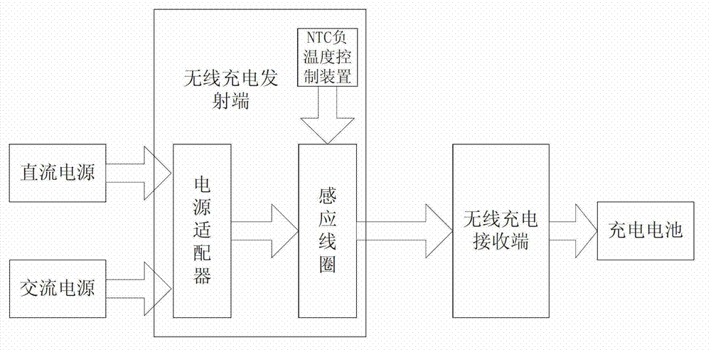
[0030] Example: see Figure 1 to Figure 2 , the wireless charging method provided by the present embodiment, which includes respectively setting a wireless charging transmitting end and a wireless charging receiving end, which includes the following steps:

[0031] (1) At the wireless charging transmitting end, a heat dissipation shell is arranged;

[0032] (2) on the inner surface of the heat dissipation shell described in step (1), a magnetic plate is set to generate magnetic induction;

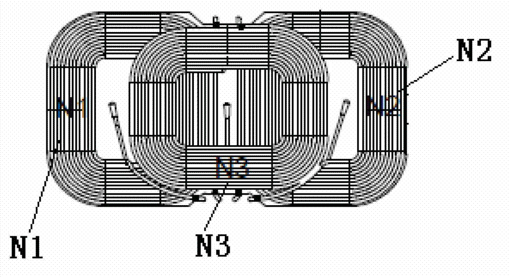
[0033] (3) Three induction coils are set, respectively N1, N2, and N3, and the induction coils are arranged in a "product"-shaped structure, wherein N1 and N2 are respectively located on the left and right sides below, and N3 is located on the top of N1 and N2. And placed in the heat dissipation shell described in step (1);

[0034] The N1, N2, and N3 coils are all set as rectangles with a specific length-to-width ratio, and the upper and lower layers are overlapped to have the highest ab...


PUM


Abstract

The invention discloses a wireless charging method. A wireless charger comprises a wireless charging emitting end and a wireless charging receiving end. The method is characterized by comprising the following steps of: (1) arranging a radiating shell at the wireless charging emitting end; (2) arranging a magnetic plate on the inner surface of the radiating shell to generate magnetic induction intensity; (3) arranging at least three induction coils, wherein the induction coils are arranged in a triangular form; (4) arranging a power adapter which is connected with the induction coils through leads and is used for supplying a working power supply to the induction coils; and (5) arranging an NTC (Negative Temperature Coefficient) control device which is connected with the coils and a charger control circuit and is used for controlling the magnitude of charging current by monitoring the temperature of a magnetic core. The invention further discloses a wireless charger for implementing the method. The method and the charger provided by the invention have the advantages of working stability, high working efficiency, high reliability, and capability of supporting high-power charging equipment.

Description

technical field [0001] The invention relates to the field of electronic information, and more to the field of power charging, in particular to a wireless charging method and a wireless charger for realizing the method. Background technique [0002] Currently, portable electronic devices, such as MP3 players, mobile phones, PDAs, etc., have rechargeable batteries therein so that users can use the portable electronic devices while moving. This type of portable electronic device is separately equipped with a charger specially used for charging the rechargeable battery, and the charger is connected to a common power source through a cable and then connected to the rechargeable battery for charging. In order for the charger to provide charging current to the rechargeable battery of the portable electronic device, the charger must be electrically connected to the rechargeable battery of the portable electronic device. In order to electrically connect the charger with the portable...

Claims


Application Information

Patent Timeline
Patent Type & Authority Applications(China)
IPC IPC(8): H02J7/00H02J7/02H01F38/14
Inventor 吴小龙周望求聂兵华
Owner 东莞市创晨电子有限公司
Why Eureka
Eureka Blog
Learn More