Wireless electric energy transmission system and constant-current and constant-voltage control method thereof

A technology of wireless energy transmission and current, applied in the direction of electrical components, circuit devices, etc., can solve the problems of adding a DC conversion circuit to increase the volume of the system, increasing the control cost and complexity, and unstable operation of the device, so as to reduce control costs and The effect of complexity, stable and reliable charging, and stable work

Inactive Publication Date: 2020-07-31
WENZHOU UNIVERSITY
View PDF6 Cites 10 Cited by
  • Summary
  • Abstract
  • Description
  • Claims
  • Application Information

AI Technical Summary

Problems solved by technology

[0004] However, there are several methods for the existing wireless power transmission device to achieve constant current and constant voltage switching charging: 1. Adopt the frequency conversion control method, that is, to make the wireless power transmission device realize constant voltage and constant current output at different frequencies, but the The frequency bifurcation phenomenon is caused, resulting in unstable operation of the device; 2. The method of adding a DC-DC converter to adjust after the secondary rectification output, but this method is not suitable for large load changes in order to avoid the occurrence of the limit duty cycle. In the case of large size, and the addition of a DC conversion circuit increases the volume of the system
3. Introduce closed-loop negative feedback control and adopt phase-shift control method in the circuit, but this method will also add too many devices, increasing control cost and complexity

Method used


Image

  • Wireless electric energy transmission system and constant-current and constant-voltage control method thereof
  • Wireless electric energy transmission system and constant-current and constant-voltage control method thereof
  • Wireless electric energy transmission system and constant-current and constant-voltage control method thereof

Examples


Embodiment Construction

[0039] In order to make the object, technical solution and advantages of the present invention clearer, the present invention will be further described in detail below in conjunction with the accompanying drawings.

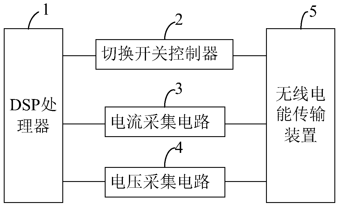
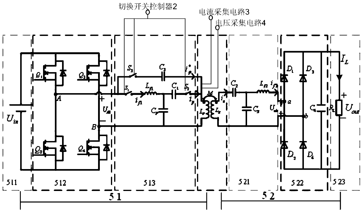
[0040] Such as figure 1 and figure 2 Shown is a wireless power transmission system provided in an embodiment of the present invention, including a DSP processor 1, a switch controller 2, a current collection circuit 3, a voltage collection circuit 4 and a wireless power transmission device 5; wherein,

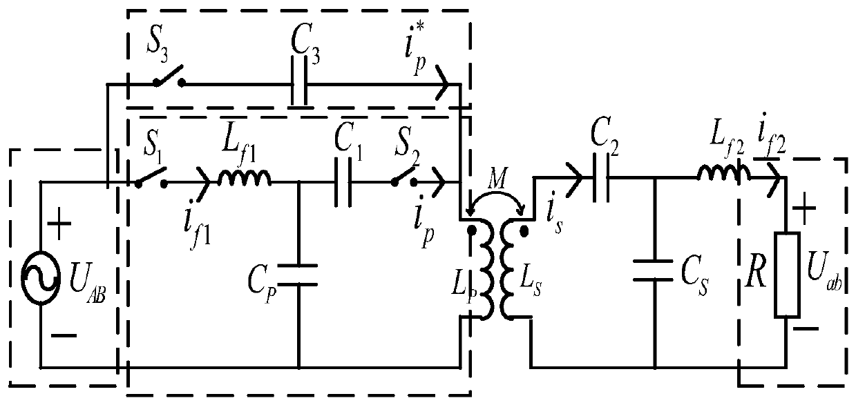
[0041] The wireless power transmission device 5 includes a transmitting module 51 and a receiving module 52 that transmits energy with the transmitting module 51 through electromagnetic induction; wherein, the transmitting module 51 includes a DC power supply 511 connected in sequence, a high-frequency inverter circuit 512, and a transmitting end compensation network 513 and the primary transmit coil L P ; The transmitter compensation network 513 includes an ind...


PUM


Abstract

The invention provides a wireless electric energy transmission system, which comprises a DSP processor, a wireless electric energy transmission device, and a change-over switch controller, a current acquisition circuit and a voltage acquisition circuit which are connected between the DSP processor and the wireless electric energy transmission device; the wireless power transmission device is arranged on a transmitting module to form a primary side LCC compensation network with change-over switches S1 and S2 and a primary side series compensation network with a change-over switch S3, and a secondary side LCC compensation network is formed on a receiving module; the change-over switch controller is connected with the change-over switches S1, S2 and S3; and the DSP processor issues a constant-current charging control instruction to the change-over switch controller, so that the change-over switch controller switches on the change-over switches S1 and S2 and switches off the change-over switch S3, and a bilateral LCC constant-current charging mode is realized; or a constant-voltage charging control instruction is issued, so that the change-over switch controller disconnects the change-over switches S1 and S2 and closes the change-over switch S3, and an S-LCC constant-voltage charging mode is realized. By implementing the invention, the defects in the prior art can be overcome, thecircuit structure is simple, and the cost is low.

Description

technical field [0001] The invention relates to the field of wireless power transmission technology and novel energy conversion technology, in particular to a wireless power transmission system. Background technique [0002] The emergence of wireless power transmission technology can effectively overcome a series of shortcomings of traditional wired power supply methods, such as: poor mobility of equipment, unsightly environment, easy contact sparks, exposure of power supply lines, etc., especially suitable for mobile equipment, electric vehicles, flammable Safe power supply for explosive environments and underwater and oil field downhole equipment. Therefore, the wireless power transmission technology is widely used in many fields. [0003] Usually, the most common load is the battery, but because the equivalent resistance of the battery is constantly changing, and its charging process includes two charging stages of constant current and constant voltage, that is, the cons...

Claims


Application Information

Patent Timeline
Patent Type & Authority Applications(China)
IPC IPC(8): H02J50/12
CPCH02J50/12
Inventor 钱祥忠徐文强寸昆屹叶静
Owner WENZHOU UNIVERSITY
Why Eureka
Try Eureka