Test method for accurately simulating bond-slip property of male pin in tensile area

A bond-slip, test method technology, applied in the testing of machine/structural components, the use of a stable shear force to test the strength of materials, measuring devices, etc., can solve problems such as the inaccurate simulation of bond-slip properties, To achieve the effect of convenient operation

Inactive Publication Date: 2010-11-03
XUZHOU UNIV OF TECH
View PDF3 Cites 0 Cited by
  • Summary
  • Abstract
  • Description
  • Claims
  • Application Information

AI Technical Summary

Problems solved by technology

[0011] (3) The yield strength of the connector material must be tested;
For studs in tension regions, the bond-slip behavior cannot be accurately simulated by push-out tests

Method used


Image

  • Test method for accurately simulating bond-slip property of male pin in tensile area
  • Test method for accurately simulating bond-slip property of male pin in tensile area
  • Test method for accurately simulating bond-slip property of male pin in tensile area

Examples


Embodiment Construction

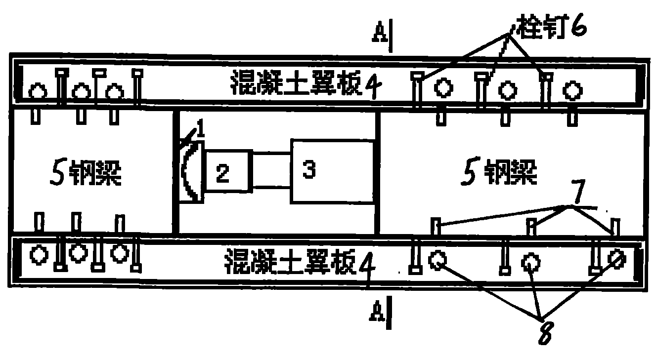
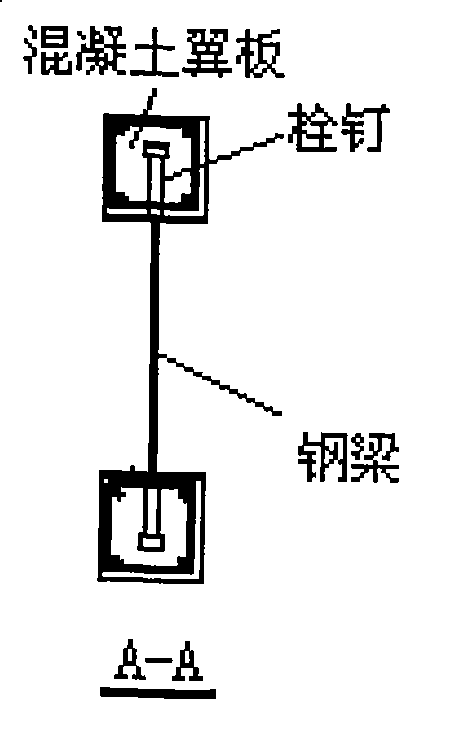
[0029] According to the current "Code for Design of Steel Structures" and the Eurocode, two sets of push-out tests are used to combine the steel beam and the concrete flange horizontally, such as figure 1 with figure 2 Shown: The establishment of a self-balancing test system established by combining two tensile specimens:

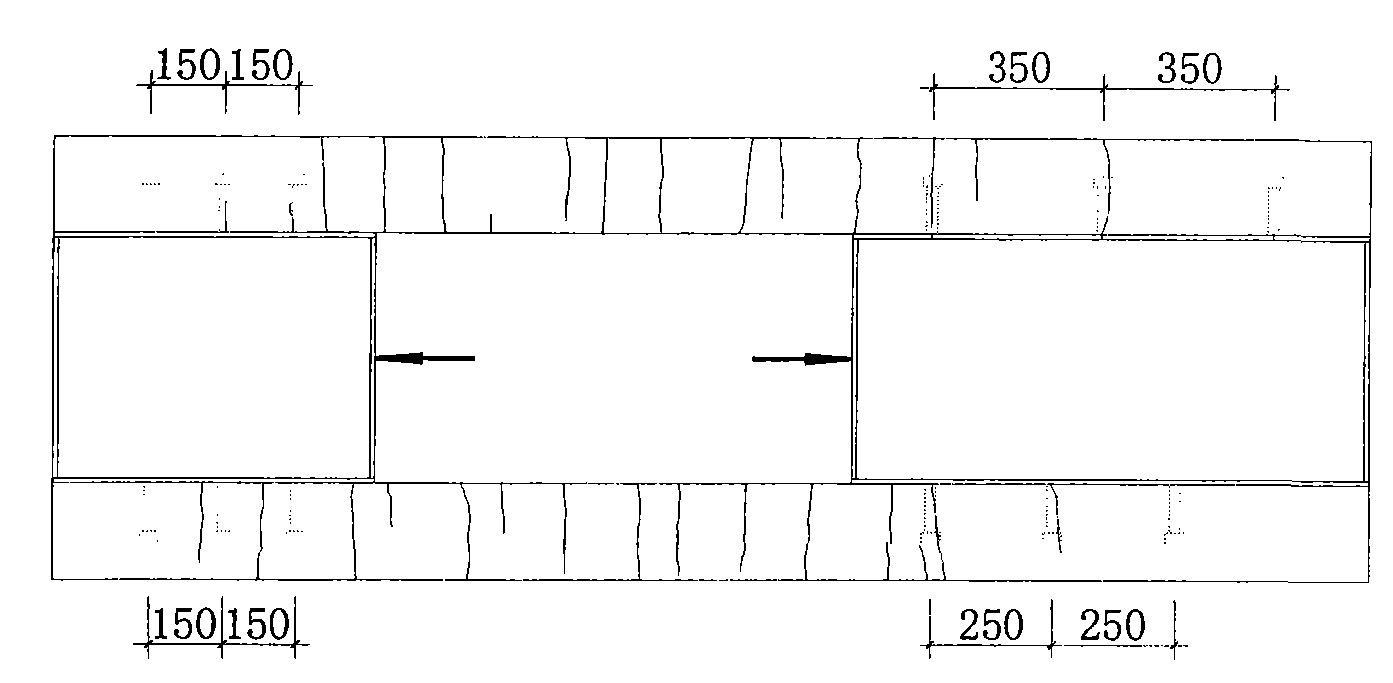
[0030] The first step is to combine the two push-out test pieces stipulated in the code, and place two steel beams 5 welded with studs 6 and the concrete wing plate formwork horizontally; in this embodiment, the upper and lower sides of each steel beam The three pegs are evenly spaced. For the convenience of installing the displacement sensor, a sensor baffle 8 is provided corresponding to each stud along the shear plane for installing the displacement sensor 7;

[0031] The second step is to pour concrete. At this time, attention must be paid to the verticality of the pre-embedded baffle and the wing; the stud 6 and the sensor baffle 8 are pre-embedded ...


PUM


Abstract

The invention discloses a test method which can accurately simulate the bond-slip properties of a stud connector in a tensile area in a combined structure. The method comprises the steps of combining two push-out samples; reserving a space for a jack between the two samples; loading through a spherical hinge; conveniently arranging a displacement sensor on a shearing surface; measuring relative slippage between a steel beam and a concrete slab, thus accurately simulating the constructive relations and the bearing capacity of the bond-slip properties of the stud connector in the tensile area of a combination beam. The method can accurately simulate the mechanical properties of the stud in the tensile area of a beam-type component in a combined structure of steel beam and concrete. Furthermore, the method is convenient to operate.

Description

technical field [0001] The invention relates to the field of structural engineering, in particular to a test method for accurately simulating the bond-slip performance of a stud in a tension zone. It is especially suitable for the test of studs in the tension zone of beam members in steel-concrete composite structures. Background technique [0002] Composite structures refer to steel-concrete composite components or structures that are connected to each other by bonding, mechanical occlusal or connectors, and can share the role of steel and concrete. As a structural form rich in innovative space, it has been greatly developed in the new century. [0003] The steel-concrete composite structure is a composite structure composed of steel beams and concrete slabs through shear connectors. The shear connectors can make the steel beams and concrete slabs work together. The shear connectors are the key components to ensure the combined effect. Due to the existence of shear connec...

Claims


Application Information

Patent Timeline
Patent Type & Authority Patents(China)
IPC IPC(8): G01N3/24G01N19/04G01M19/00G01M99/00
Inventor 殷惠光王景全陈柏林姜慧李国富李雁朱炯雷金果
Owner XUZHOU UNIV OF TECH
Why Eureka
Try Eureka