

Movement guiding device
A motion guidance, rolling groove technology, applied in the direction of linear motion bearings, bearings, shafts and bearings, etc., can solve problems such as damage to the scooping part and the shape effect of the pointed arch groove becoming smaller.
Active Publication Date: 2008-12-03
THK CO LTD
View PDF3 Cites 3 Cited by
- Summary
- Abstract
- Description
- Claims
- Application Information
AI Technical Summary
Problems solved by technology
As a result, the effect of forming the pointed arch groove shape is also reduced
Therefore, if the ball is rotated at a high speed, the scooping part may be damaged
Method used
View moreImage
Smart ImageViewing Examples

Examples
Embodiment
[0110] The inventor manufactured the ball spline of the first embodiment, and conducted a high-speed durability test. The scooping of the conventional end cover was damaged at 1,000km, but the scooping part of the high-speed end cover was not damaged even if it traveled 10,000km.
[0111] This specification is based on Japanese Patent Application No. 2005-318110 filed on November 1, 2005. That content is all contained here.
Login to View More PUM
 Abstract
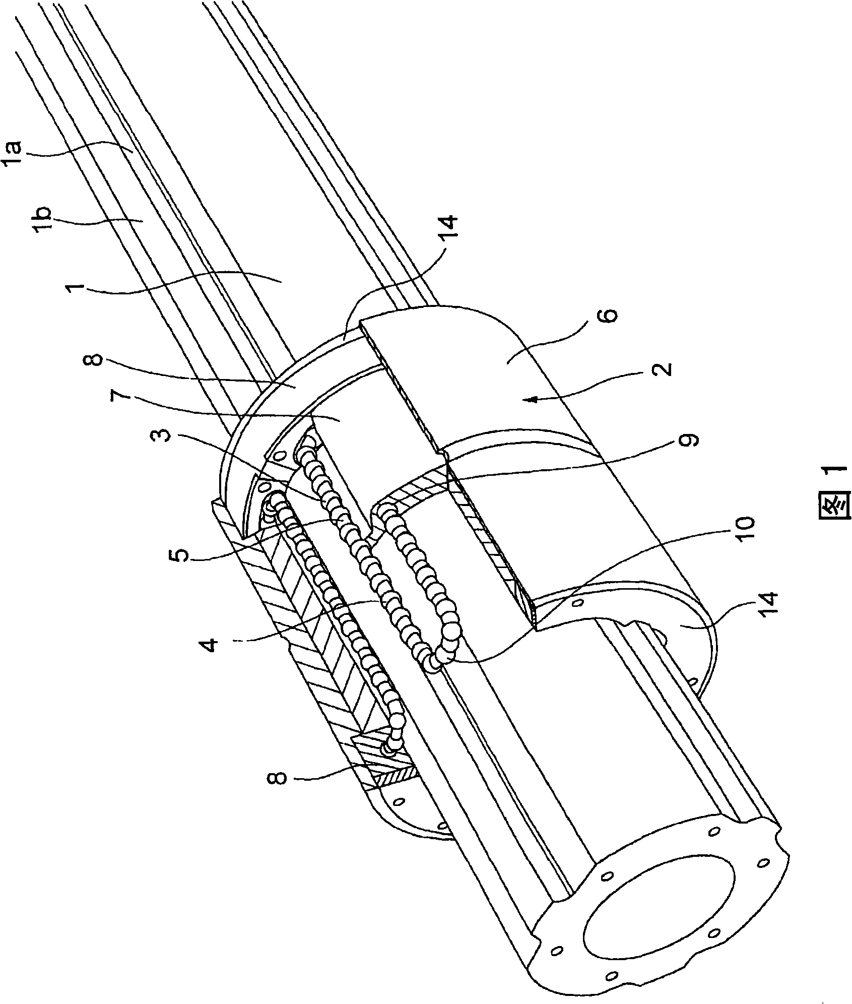
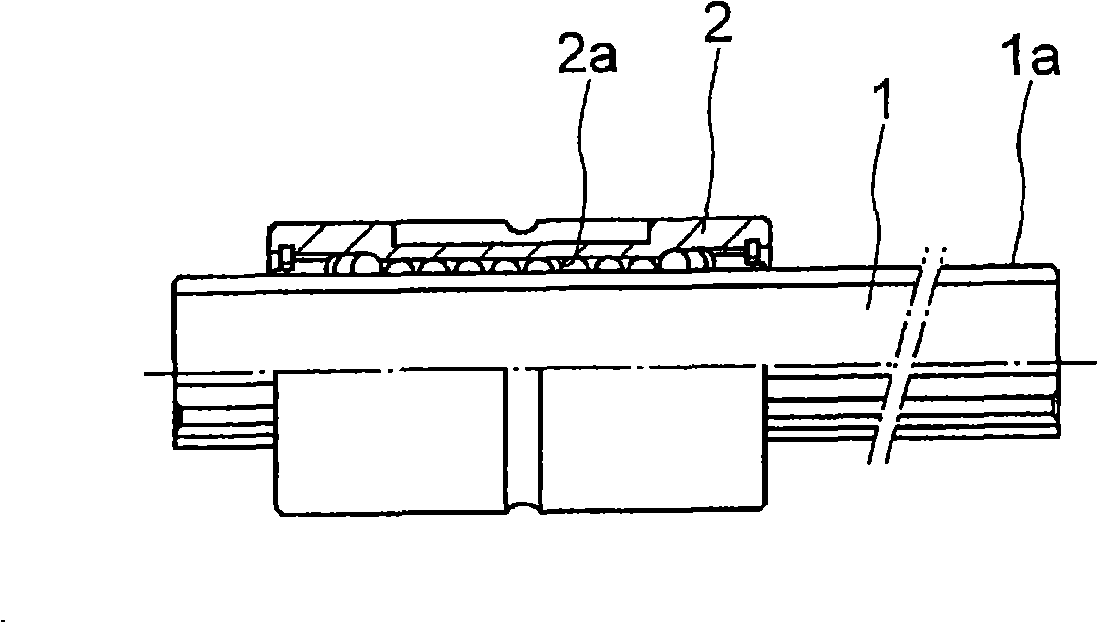
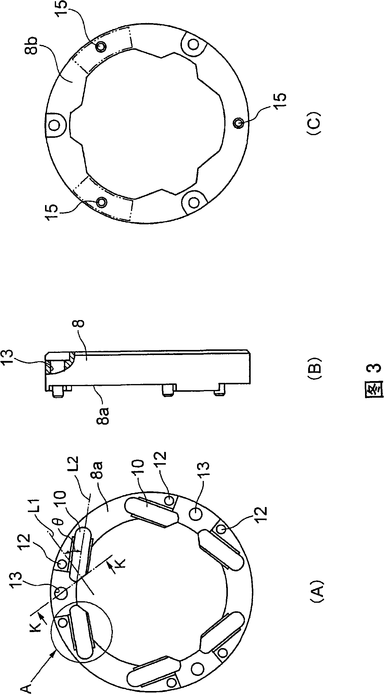
A movement guiding device in which there is no possibility that a pickup part is broken even if a movement member is moved at a high speed. When viewed from the axial direction of a track axis (1), a direction changing passage (10) is tilted relative to a contact angle line (L1)(line connecting the bottom (P1) of a ball rolling groove (1a) to the center (C) of a ball (3)). The cross section of the direction changing passage (10) including the pickup part (17) is formed in a Gothic arch groove shape formed of two circular arcs (R1) so as to come into contact with the ball (3) at two points. Then, the direction changing passage (10) is twisted so that the locus (18) of the top of the Gothic arch groove shape nears the contact angle line (L1) at the pickup part (17).
Description
technical field [0001] The present invention relates to a motion guide device such as a linear guide or a ball spline capable of moving a moving member relative to a rail member. Background technique [0002] Motion guidance devices are embedded in robots, machine tools, and semiconductor and liquid crystal manufacturing equipment to guide the linear or curved motion of moving objects. [0003] A linear guide, a ball spline, etc. are known as one type of motion guide device. linear guides such as Figure 24 As shown, a track rail 31 formed with a ball rolling groove 31 a and a moving block 33 assembled so as to be slidable along the track rail 31 via a plurality of balls 32 are provided. A plurality of loaded ball rolling grooves 32 a facing the ball returning path of the track guide rail 31 , and a ball returning path 38 extending parallel to the loaded ball rolling grooves 32 a are formed in the moving block 33 . A pair of end plates 34 are attached to both ends of the m...
Claims
Login to View More Application Information
Patent Timeline
 Patent Type & AuthorityApplications(China)
IPC IPC(8): F16C29/06
CPCF16C29/0647F16C29/0609F16C29/0695
Inventor望月广昭村田智纯咲山隆
OwnerTHK CO LTD