Objective table of multi-mode imaging system

A technology of multi-modal imaging and stage, applied in the field of stage

Active Publication Date: 2008-12-10
SYMBOW MEDICAL TECH
View PDF0 Cites 13 Cited by
  • Summary
  • Abstract
  • Description
  • Claims
  • Application Information

AI Technical Summary

Problems solved by technology

At present, high-precision electronically controlled stages include: translation stage (horizontal direction), rotary stage (circumferential direction), lifting stage (vertical direction), angle stage (precision angular displacement) and electric multi-dimensional combination stage, but these devices cannot Meet the above three requirements at the same time

Method used


Image

  • Objective table of multi-mode imaging system
  • Objective table of multi-mode imaging system
  • Objective table of multi-mode imaging system

Examples


Embodiment Construction

[0016] The present invention will be described in detail below with reference to the accompanying drawings and embodiments.

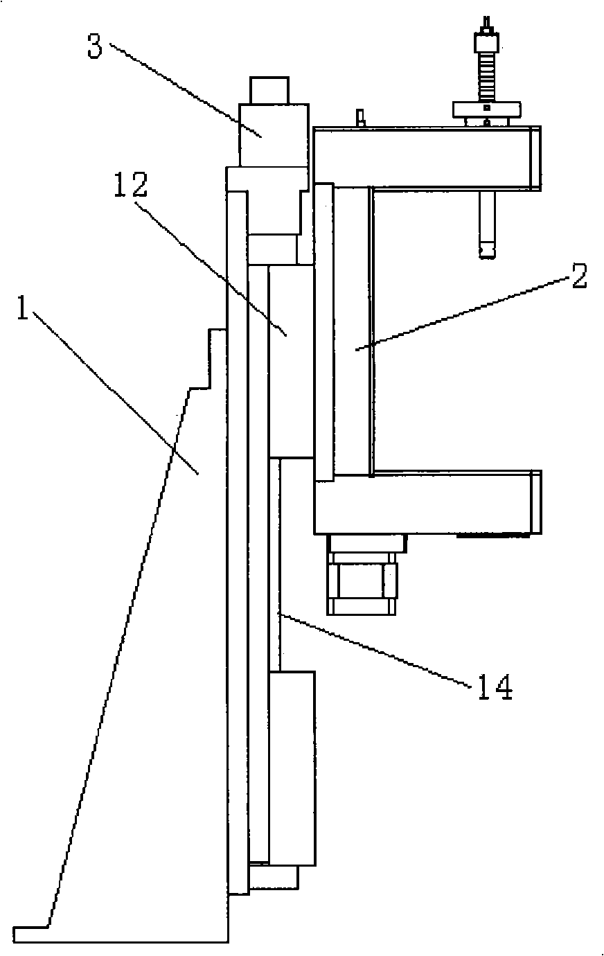
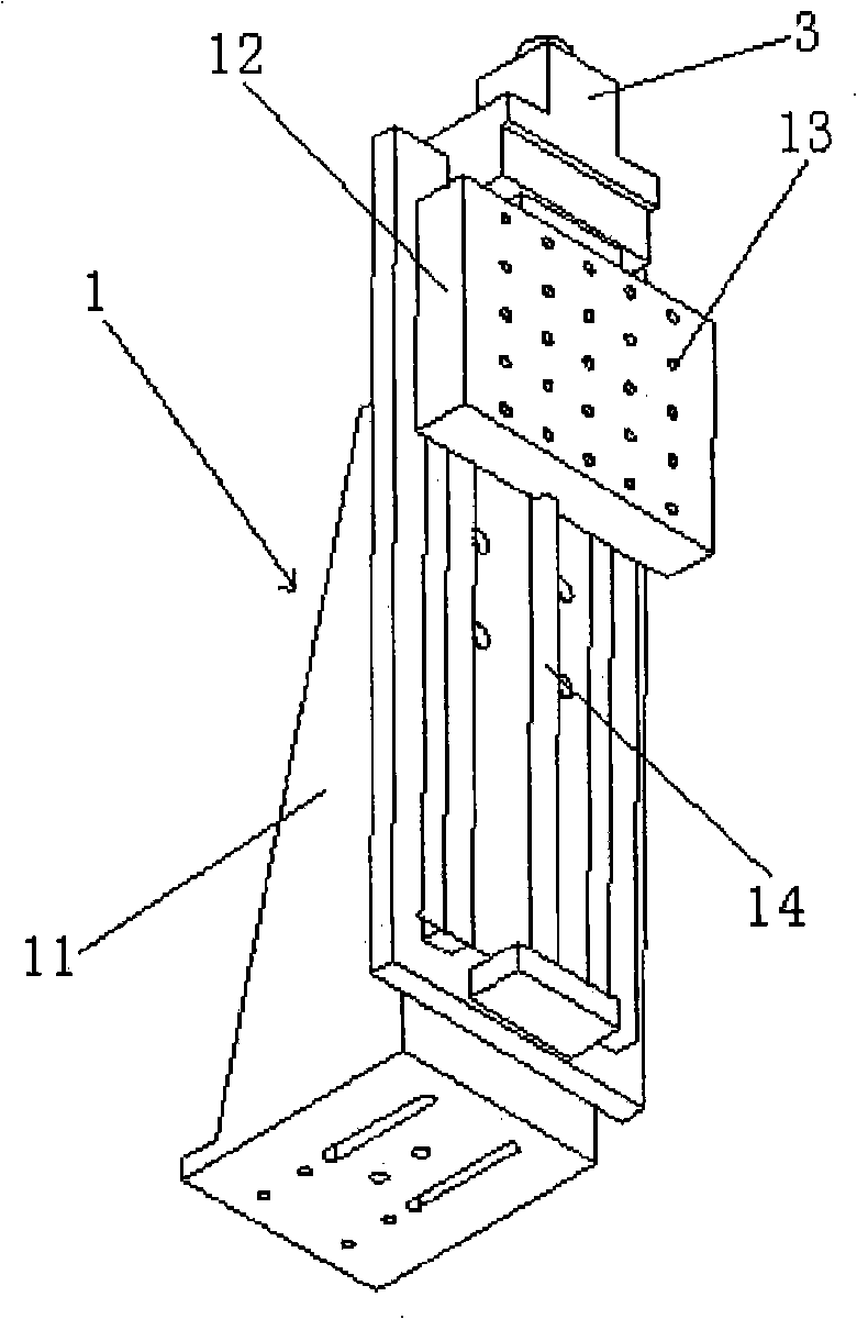
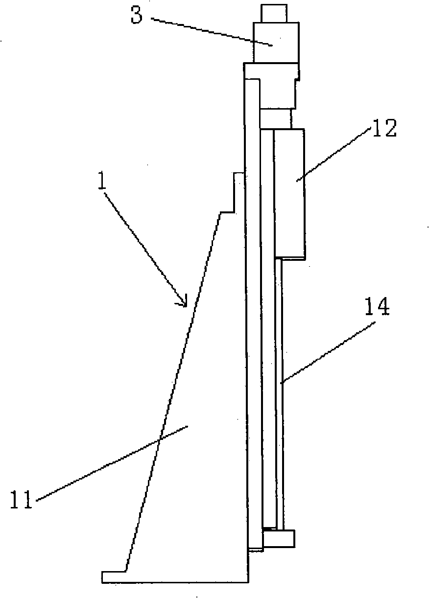
[0017] like figure 1 , figure 2 , image 3 As shown, the present invention includes a lifting platform 1 and a rotating table 2, the lifting platform 1 includes a lifting platform bracket 11, and the lifting platform bracket 11 is provided with a sliding block 12 that uses a double guide (or a single rail) rail to slide, The slider 12 is provided with a number of fixing holes 13 connected with the rotary table 2, the motor 3 is fixedly connected to the lifting table bracket 11, the motor 3 is connected to the slider 12 through the transmission screw 14, and the slider 12 is connected to the slider 12 through the motor 3 (or through the transmission). ) drives the transmission screw 14 to rotate to realize the lifting movement, and the stroke of the slider 13 is 250mm (this is only an example, not limited to this).

[0018] like Figure 4 , Figure...


PUM


Abstract

The invention relates to an object stage of a multi-modal imaging system, which is characterized in that a lifting table and a slide device are arranged on a revolving stage of the lifting table; a slide block mechanism of a screw mandrel is arranged on the lifting table; the revolving stage is fixed on a slide block; the slide block mechanism of the screw mandrel drives the revolving stage to do up-and-down movement on the lifting table; the revolving stage comprises a mounting bracket; a driving gripper mechanism is arranged on the mounting bracket; the driving gripper mechanism comprises a hollow shaft driven by an electronic motor via a transmission mechanism; the upper end of the hollow shaft is communicated with an inhalator anesthesia apparatus via an anesthetic gas pipe; the lower end of the hollow shaft is provided with a gripper used for fixing a small animal; a driven gripper mechanism corresponding to the driving gripper mechanism is arranged on the mounting bracket; and the driving and the driven gripper mechanisms revolve synchronously. The object stage of the multi-modal imaging system can not only ensure that each detector in the multi-modal imaging system can acquire the full circular information of a tested object, but also keep the vital sign of the tested object in optimum conditions all the time, thus ensuring that the process of multi-modal imaging goes smoothly.

Description

technical field [0001] The present invention relates to a stage, in particular to a stage of a multimodal imaging system. Background technique [0002] Multimodal imaging is the current development trend of medical imaging. Imaging technologies of different modalities can provide different information, such as PET / CT technology, PET images provide functional information of organisms, and CT images provide structural information of organisms. Combining the information leads to an exact understanding of the functional state at a certain location in the organism. Single-modality imaging can only observe one aspect, while multi-modality imaging can simultaneously observe two or more tissue information in an organism, which is crucial for studying the interaction between different systems in an organism. Multimodal imaging makes real-time dynamic observation of biological response changes in biological organisms a reality, opening a black box window for a profound understanding ...

Claims


Application Information

Patent Timeline
Patent Type & Authority Applications(China)
IPC IPC(8): A61B6/04A61B6/03A61M16/01
CPCA61B6/508
Inventor 王维平周立涛张岳海
Owner SYMBOW MEDICAL TECH
Why Eureka
Try Eureka