

Air insulated isolation switch device
A disconnector and gas-insulated technology, which is applied to air switch components, emergency protection devices, switches with movable electrical contacts, etc., can solve the problem that the connecting parts cannot realize direct connection and three-phase linkage, disassembly, complicated installation, etc. Reliable performance, stable operation, and uniform electric field distribution can be achieved without problems such as a large number of parts
- Summary
- Abstract
- Description
- Claims
- Application Information
AI Technical Summary
Problems solved by technology
Method used
Image

Examples
Embodiment 1
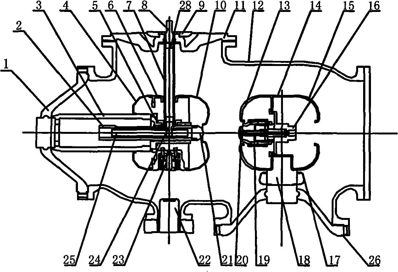
[0022] Such as figure 1 As shown, a linear isolating switch device, the isolating switch is linear, using gear, rack drive, including filled with SF 6 Housing 12 of insulating gas, a isolating switch and a grounding switch, the moving end of isolating switch includes shielding conductor 3, moving end shielding cover 4, moving contact shielding cover 10, moving contact seat 5, shielding cover conductor 6, vertical Insulation rod 7, operating shaft 8, pinion shaft 24, moving contact 21 of isolating switch and rack 25, etc.; static end part includes static contact shield 13, shield conductor 14, static end shield 15, static contact Seat 16, conductor shield 17, conductor 18, contact finger 19 and static contact 20. The grounding switch static end 23 is housed on the moving end portion shielding cover conductor 6, and the grounding switch moving end 22 is fixed on the lower small support tube in the housing 12.
[0023] The movable end part of the isolator is fixed on the housin...
Embodiment 2
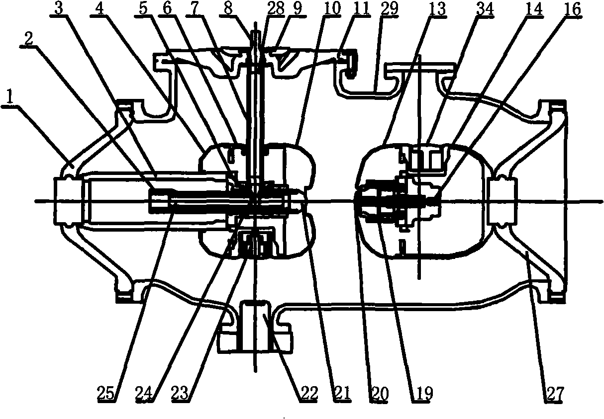
[0026] Such as figure 2 As shown, it is another linear isolating switch device, the moving terminal of the isolating switch and figure 1 The same, but another arrangement for the static end part according to the different wiring methods, that is, the insulating basin 27 of the static end part of the disconnector and the insulating basin 1 of the moving end are in the same horizontal direction and fixed at both ends of the housing 12. The static contact 20 is fixed on the static contact seat 16, and is connected with the shield conductor 14 and fixed to the static end part. In this arrangement, there is an additional shielding conductor 34 on the shield conductor 14 at the static end. According to different wiring methods, the shielding conductor 34 can be used as the static end part of the quick grounding switch, and the corresponding small size of the housing 12 The moving contact part of the quick earthing switch and the operating mechanism of the quick earthing switch can...
Embodiment 3
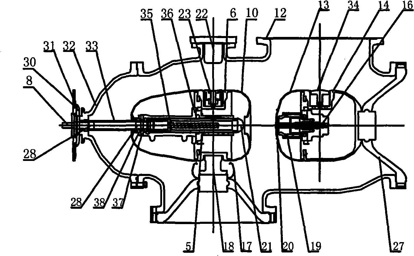
[0028] Such as image 3 As shown, it is a right-angle isolating switch device, which adopts a gear and lead screw transmission mechanism, including a housing 12, an isolating switch, and a moving and static end part of an earthing switch. The moving end of the isolating switch includes an operating shaft 8, flanges 30, 31 , 32, insulating pull rod 7, lead screw 33, conductor 36, moving contact seat 6 and moving contact 21, etc., the static end part and figure 2 Same. The moving end part of the isolator is fixed on the housing 12 through an insulating basin 29 , and the operating transmission mechanism is fixed on the housing 12 through a hat-shaped flange 32 . The operating mechanism of the isolating switch drives the operating shaft 8 to rotate. The operating shaft 8 is connected to the horizontal insulating pull rod 33 through the left end connecting piece 28, and the horizontal insulating pulling rod 33 is connected to a nut through the right end connecting piece 28. The ...
PUM
 Abstract
Description
Claims
Application Information