Packing case

A packing box and box body technology, which is applied in the directions of packaging, transportation, packaging, display stands, etc., can solve the problems of increased work load, obstruction of hooks, complicated work of packing boxes, etc., and achieve the effect of reducing the work load

Inactive Publication Date: 2008-12-17
MAX CO LTD
View PDF2 Cites 1 Cited by
  • Summary
  • Abstract
  • Description
  • Claims
  • Application Information

AI Technical Summary

Problems solved by technology

[0008] However, in the case of forming the hook part by the above method, although there is an advantage that the hook part will not hinder the closing of the upper cover when the hook part is hung on the hanging rod for display, there is the following problem: when the hook part is not hung on the hanging rod When displaying products on a display shelf instead of a stick, the protruding hook will become an obstacle
Therefore, there is a problem that the arrangement state of the displayed packaging boxes is confused due to the erected hooks, and the work of storing the packaging boxes in a large box is complicated.
[0010] In addition, it is preferable to store the hook portion in the packing box without protruding to the outside of the packing box. However, when the upper edge portion of the corresponding other side wall portion is extended to form the hooking portion as described above, if the hooking portion If it is stored inside the packing box, it is difficult to insert the insertion portion formed at the end of the cover body into the packing box, which hinders the closing of the upper cover.
[0011] In the case of fixing the storage member provided with the hook portion to the inner wall of the packing box, although the hook portion can be accommodated in the packing box while the insertion portion can be inserted into the packing box by properly designing the fixing portion, However, it is necessary to fix the storage member provided with the hook portion to the inner wall surface of the packaging box, so there is a problem that the work load for forming the hook portion on the packaging box increases.

Method used


Image

  • Packing case
  • Packing case
  • Packing case

Examples


Embodiment Construction

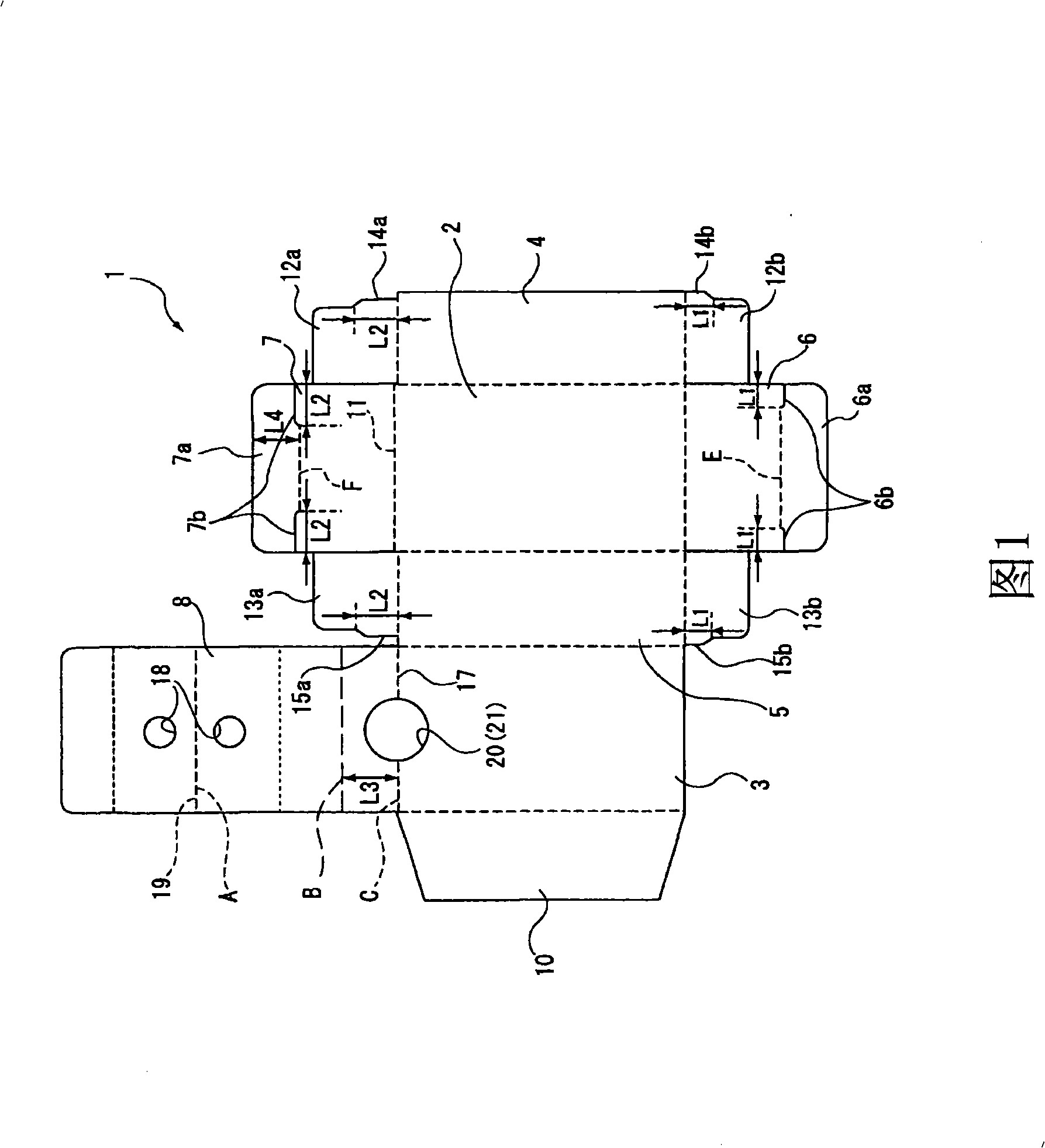
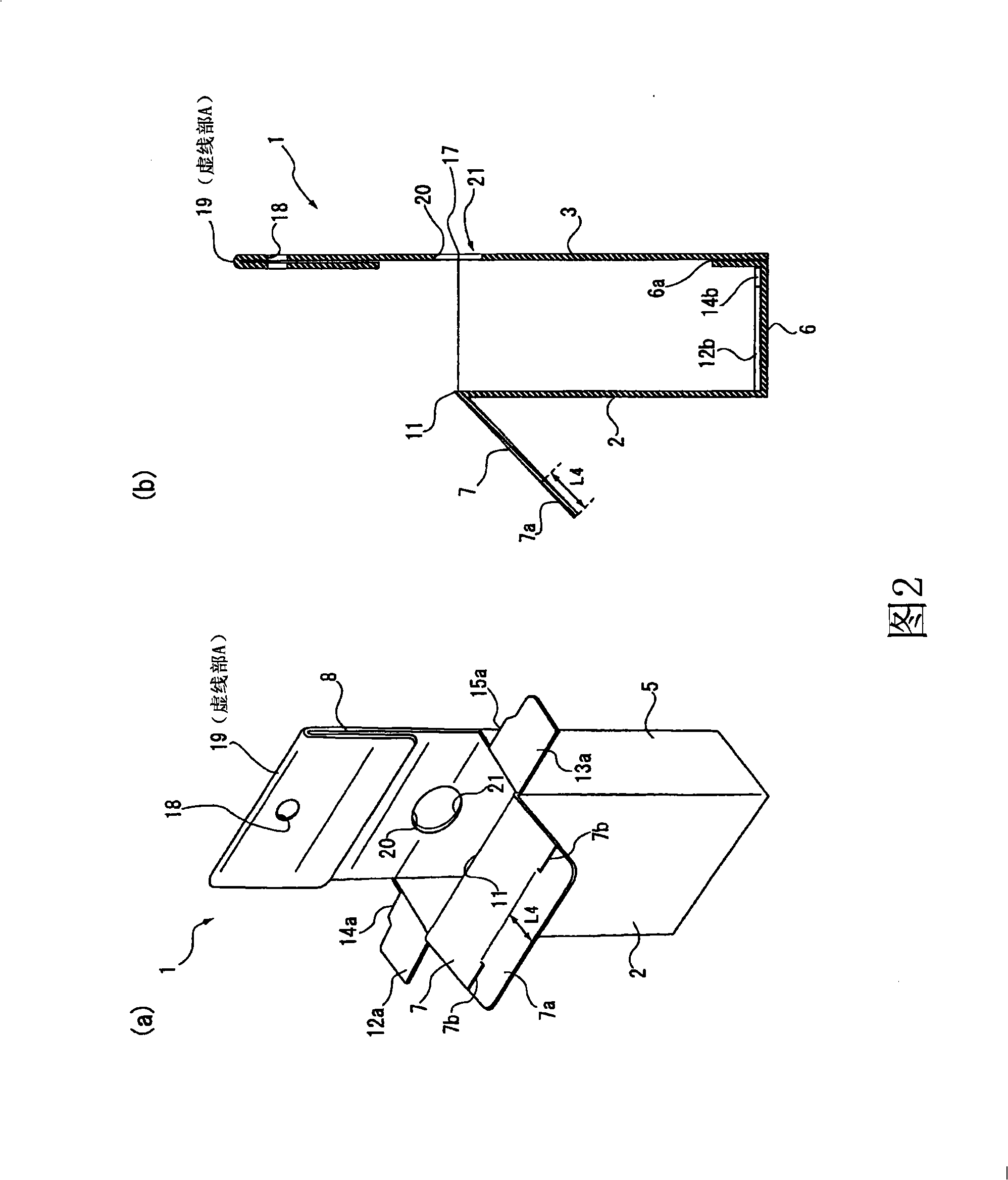
[0027] The packaging box of the present invention will be described in detail below with reference to the accompanying drawings. Fig. 1 shows a developed view of the packaging box of the present invention. Fig. 2(a) shows a front perspective view showing a state in which the packing box is formed into a rectangular cylindrical shape with a bottom by assembling the expanded view shown in Fig. 1 , and Fig. 2(b) shows a side sectional view thereof.

[0028] The packing box 1 roughly includes four rectangular side portions 2 to 5 , a bottom portion 6 , an upper surface portion (lid portion) 7 , and a hook portion 8 . As shown in FIG. 1 , the packing box 1 is formed of a sheet of paper, and the above-mentioned four side parts 2 to 5, the bottom part 6, the upper surface part 7, and the hook part 8 are integrally formed.

[0029] The four side parts 2 to 5 are composed of a front part 2 and a back part 3 in a wide rectangular shape, and a right side part 4 and a left side part 5 in...


PUM


Abstract

A hanging part can be simply formed in the packing case of the invention, in addition, the open and close of a cover can be conveniently and actually performed while containing the hanging part into the packing case even without using the hanging part in the exhibiting process. The cover part (7) of the packing case (1), which is capable of being bent, opened and closed, can be formed on an upper edge part (11) of the case body in rectangular and barrel shape. The cover part (7) serves as an upper surface of the case body, an inserting part (7a) is formed on an end of the cover part (7). The inserting part (7a) and another upper edge part (17) opposite to the upper edge part (11) are inserted into the inner side of the case body to prevent the easy open of the cover part (7). The hanging part (8) is formed in such a manner that the hanging part is bent towards the inner part of the case body on the upper edge part (17), one end of the hanging part is turned back along the direction the upper edge part (17), and the front end part of the hanging part protrudes upwards from the upper edge part (17).

Description

technical field [0001] The present invention relates to a packaging box, and more specifically, to a packaging in which a hanging rod or the like installed in a display place is engaged with a hook portion extending from the upper edge of the box body so as to hang and display the goods stored inside box. Background technique [0002] In the past, the following methods have been used as a method for displaying goods stored in packaging boxes for display at a store: a method of arranging packaging boxes on a display rack; method on a hanging stick. [0003] In particular, when the goods stored in the packing box are small and light, the method of hanging and displaying the packing box by a hanging rod is often adopted. [0004] In this way, the hanging part for fastening with the hanging rod is provided on the hanging display packing box. A general packaging box adopts the following structure: a top cover is provided on one upper edge of the packaging box, and the opposite...

Claims


Application Information

Patent Timeline
IPC IPC(8): A47F7/03B65D25/22B65D5/06B65D5/00
Inventor 神明进
Owner MAX CO LTD
Why Eureka
Try Eureka