

Protection system for light passive network
A protection system and passive network technology, applied in the field of optical passive network, can solve the problem of expensive protection system, and achieve the effect of simple network, easy promotion and use, and simple network structure
Inactive Publication Date: 2008-12-17
SHANGHAI BROADBAND TECH
View PDF0 Cites 8 Cited by
- Summary
- Abstract
- Description
- Claims
- Application Information
AI Technical Summary
Problems solved by technology
The traditional design requires active and standby protection of optical fibers on the backbone side (OLT to optical splitter, OLT is the optical line terminal) or user side (optical splitter to ONU, ONU is the optical network unit); the entire protection system needs To add an additional optical splitter, each ONU also needs to add an optical coupler to connect the main and standby optical fibers respectively; resulting in a very expensive PON protection system
Method used
View moreImage
Smart ImageViewing Examples

Examples
Embodiment 1
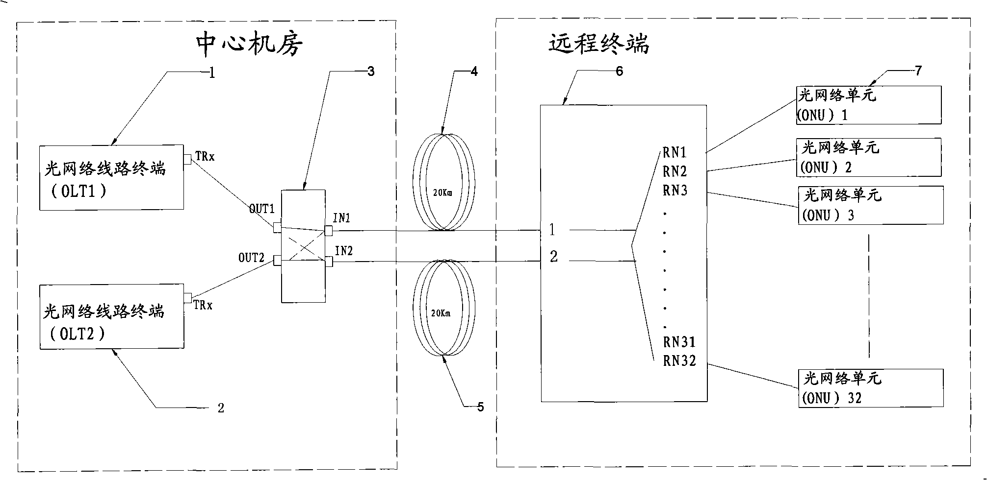
[0032] Such as image 3 , when the OLT encounters failures such as power failure or system crash, the optical fiber line protector detects the change of the output light intensity of the OLT, and when it is less than the set threshold, it will automatically switch to the backup OLT to ensure the normal operation of the system .
Embodiment 2
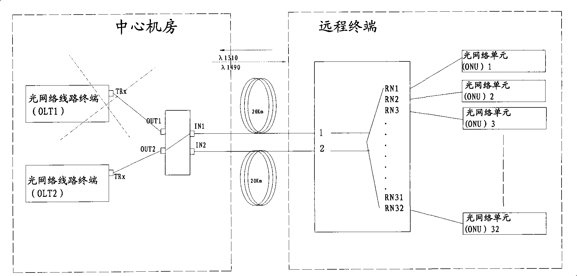
[0034] Such as Figure 4 , when the backbone optical fiber is damaged due to careless construction or other reasons, the upstream optical signal of the ONU detected in the fiber optic connection to bring the system back to normal operation.
Login to View More PUM
 Abstract
The invention relates to an optical passive network protecting system, comprising: a main optical network terminal, a standby optical network terminal, a fiber circuit protecting structure, an optical splitter, an optical network unit, wherein the main optical network terminal is connected with an input end 1 or an input end 2 through the fiber circuit protecting structure. The standby optical network terminal is connected with an input end 1 or an input end 2 of the optical splitter through the fiber circuit protecting structure. The output end of the optical splitter is connected with the optical interface of the optical network unit. Compared with the traditional technique, the invention provides a plurality of protections for the PON system, with lower cost.
Description
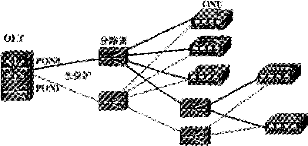
technical field [0001] The invention relates to an optical passive network, in particular to an optical passive network protection system. Background technique [0002] Among the current access technologies, PON (Optical Passive Network) is the most concerned. As the user scale expands, the protection of optical fiber links is very important. [0003] Such as figure 1 , the general PON network adopts a complete protection method. Once the optical fiber in the link is interrupted, the system will automatically switch to the backup optical fiber. The traditional design requires active and standby protection of optical fibers on the backbone side (OLT to optical splitter, OLT is the optical line terminal) or user side (optical splitter to ONU, ONU is the optical network unit); the entire protection system needs To add an additional optical splitter, each ONU also needs to add an optical coupler to connect the main and standby optical fibers respectively; resulting in a very ...
Claims
Login to View More Application Information
Patent Timeline
 IPC IPC(8): H04J3/08
Inventor李毅刘浩锋
OwnerSHANGHAI BROADBAND TECH