

Elliptical trainer with adjustable pedal track
An elliptical exercise machine and trajectory technology, applied in sports accessories, training equipment for adjusting coordination, training equipment for adjusting cardiovascular system, etc., can solve the problems of low working efficiency, high production cost and electricity, complex appearance, etc. High working efficiency and good appearance
Active Publication Date: 2010-11-24
JOHNSON HEALTH TECH
View PDF1 Cites 1 Cited by
- Summary
- Abstract
- Description
- Claims
- Application Information
AI Technical Summary
Problems solved by technology
From a mechanical point of view, this frame body 95 can be regarded as a "first type of lever", wherein, since the length between the point of application of the driving device 96 and the pivot point 97 of the frame body (ie, the force arm) is smaller than that of the cantilever arm 94 The length (i.e., the resistance arm) between the suspension point and the pivot point 97 of the frame makes the working efficiency of the driving device 96 relatively low, so a motor with a large output force is required, resulting in relatively low production cost and consumed electric power. high
It should be noted that, under such circumstances, directly moving the pivot point 97 on the elevated frame body 95 to change the ratio of the force application arm to the force resistance arm is not an ideal method to solve the above-mentioned problem, because this method will Shortening the deflection range at the top of the cantilever 94, increasing the space requirement of the driving device, and reducing the response efficiency when adjusting the trajectory, in short, the disadvantages outweigh the advantages
(2) In addition, under the above-mentioned structure, the driving device 96 is generally arranged in the center between the left and right (enabling symmetrical force on the aforementioned U-shaped frame), therefore, when the relative relationship of the components is set at the design stage , in order not to interfere with the driving device 96 at the bottom (and the protective case cover not shown in the figure), and to keep a safe distance from accidents of pinching, the height of the lowest point of the support rod 92 must be moderately increased, causing the pedal 91 is supported to move to a higher position, thus affecting the user's convenience when boarding the pedal 91 and the sense of security when exercising
Although this design maintains the design requirement that the support rod 92 and the pedal 91 be kept as low as possible by moving the drive device 96 from the bottom of the support rod 92 to the side, but the production cost is further increased due to the use of two sets of drive devices 96
At the same time, even though the output requirements of each driving device under this structure are relatively low, the aforementioned problem of arm ratio still exists, so the working efficiency of each driving device is still low and cannot be effectively used.
In addition, in another conventional structure similar to that shown in Figure 12, the pivot point of the frame body is located at the bottom end, and the driving device directly pushes and pulls the top of the frame body, that is, the force arm and the resistance arm are of equal length. The working efficiency of the driving device with this structure is still not ideal
(4) In addition to the problem of working efficiency, the aforementioned cantilever structure also has room for further improvement in terms of stability
In the various known elliptical exercise machines with adjustable pedal tracks, the driving device is not well integrated with the existing structure. In addition to the need to design an additional cover to cover and cover, resulting in increased cost, increased volume, and complicated appearance, What's more serious is that as mentioned earlier, in design, because other components have to dodge or pull the driving device, the degree of freedom of design and ergonomic characteristics are reduced
Furthermore, in the various known elliptical exercise machines that can adjust the pedal trajectory, the user can only know the current slope of the pedal trajectory through the electronic data displayed on the console, and cannot intuitively observe the spatial relationship of the main components of the exercise machine. visual judgment
What's more, most of the adjustment components (such as cantilever and support body) in most known structures are not located in front of the user's eyes, so that the adjustment of the slope of the pedal track is not intuitive enough, but must be obtained through data.
Method used
View moreImage
Smart ImageViewing Examples

Examples
Embodiment Construction
Login to View More PUM
 Abstract
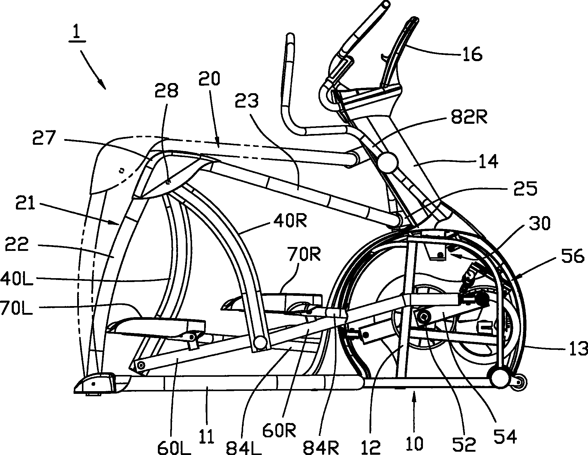
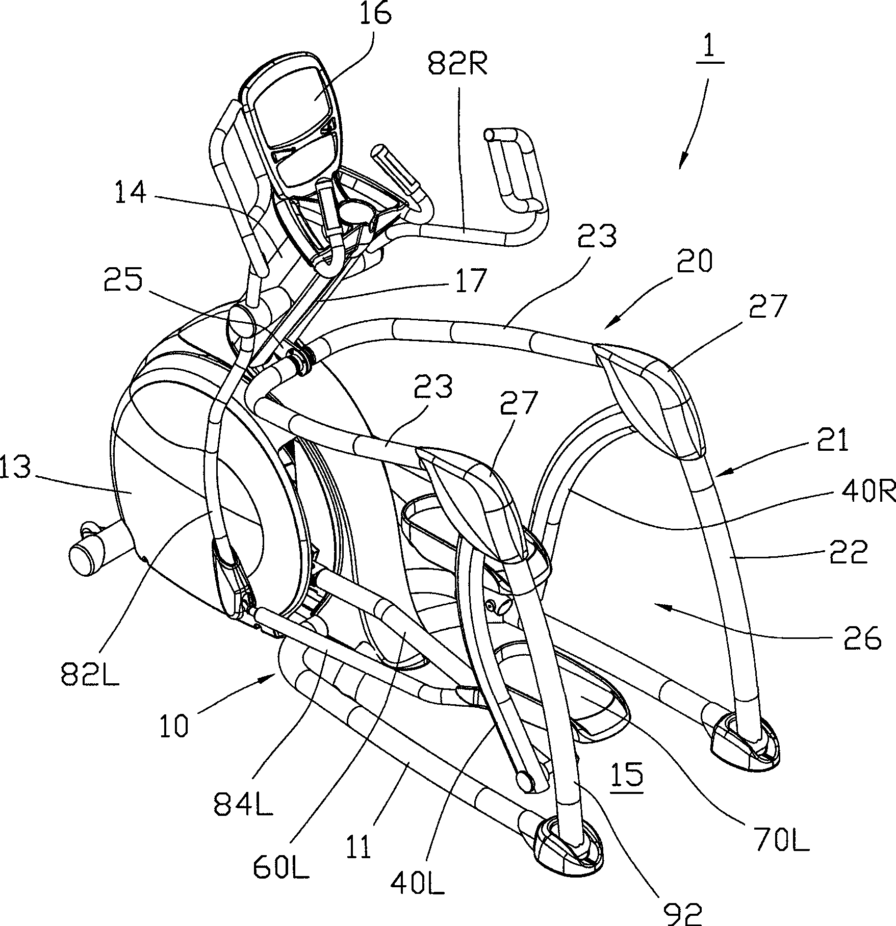
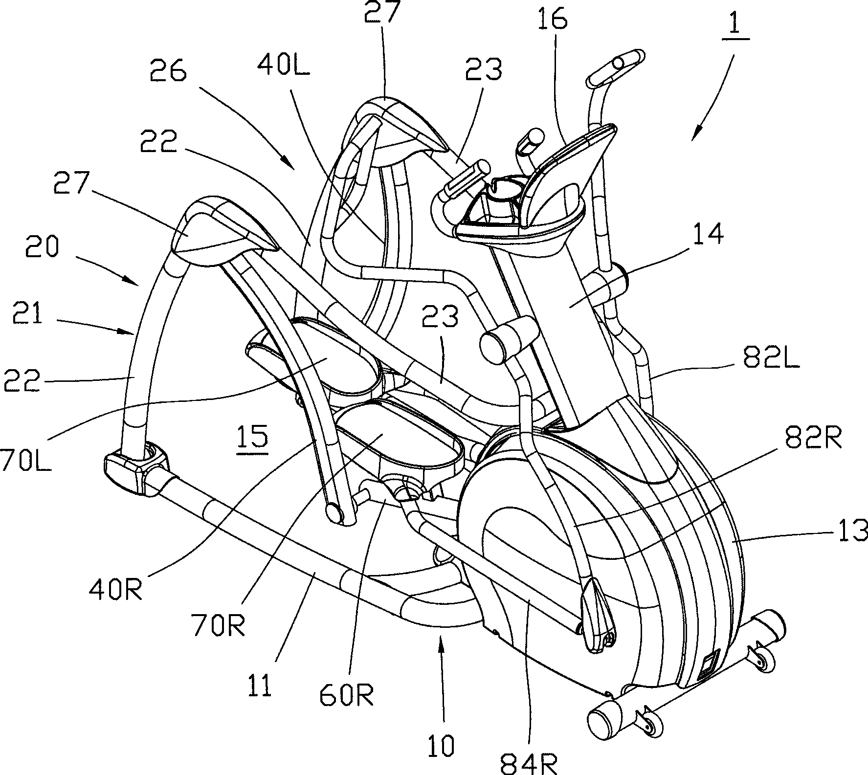
The present invention relates to an elliptical sports machine with the tread-board orbit being adjustable, which comprises a skeleton, a movable bracket, a driving device, a right suspension arm, a left suspension arm, a right supporting rod, a left supporting rod, a right tread-board and a left tread-board, wherein, the movable bracket is provided with a right bracket body and a left bracket body, which are connected with each other through a motion part, and both the right and the left bracket bodies are provided with a bearing part and a rotation-shaft part, which are arranged at the back of the motion part; the rotation-shaft parts of the bracket bodies are coaxially hinged to the skeleton; the straight-line distance between the rotation-shaft part of the bracket bodies and the motionpart is more than the straight-line distance between the rotation-shaft part and the bearing part; the driving device is arranged on the skeleton and is provided with a motor, and the force output thereof is connected with the power of the motion part of the movable bracket; both the right and the left suspension arms are provided with a suspension end and a swinging end; each of the right and the left supporting rod is provided with a return-winding part and a swinging part that is arranged after the return-winding part, and the return-winding part moves on a closed orbit corresponding to the skeleton, and the swinging part is hinged on the swinging end of the corresponding suspension arm; each of the right and the left tread-boards is respectively supported by the two supporting rods directly or indirectly. The driving device has high work doing efficiency; moreover, with the elliptical sports machine, the user can directly acknowledge of the inclined degree of the tread-board orbit.
Description
Elliptical exercise machine with adjustable pedal trajectory technical field The present invention relates to exercise and fitness equipment, in particular to an elliptical exercise machine (Elliptical) with adjustable pedal tracks. Background technique The elliptical exercise machine is a kind of sports and fitness equipment that can carry the user's feet with the left and right pedals, and then guide the feet to move on an elliptical trajectory. In the prior art, the pedal trajectory of some elliptical exercise machines can be adjusted by the user according to individual needs, so as to change the stride range, exercise difficulty or exercise parts. As shown in Figure 12, it is a known elliptical exercise machine 9 with adjustable pedal tracks (note: for details, please refer to the Chinese No. 1958099 early published patent case), the action principle of its relevant parts is as follows: Supported by the support rods 92 extending forward and backward, the front ends o...
Claims
Login to View More Application Information
Patent Timeline
 Patent Type & AuthorityPatents(China)
IPC IPC(8): A63B22/04
CPCA63B2022/0041A63B22/001A63B2022/0676A63B2071/025A63B22/0015A63B21/225A63B2022/0038A63B22/0664
Inventor马克·康乃尔
OwnerJOHNSON HEALTH TECH