Mechanical type automatic rail gripping apparatus

A mechanical and automatic technology, applied in the field of spreaders, can solve the problems of inconvenient operation, inconvenient operation, high cost, etc., and achieve the effects of high economy and practicability, simple, lightweight and reliable structure, and a wide range of applications.

Inactive Publication Date: 2008-12-24
武汉凯盟机电工程有限公司
View PDF0 Cites 6 Cited by
  • Summary
  • Abstract
  • Description
  • Claims
  • Application Information

AI Technical Summary

Problems solved by technology

Some use a four-bar linkage mechanism to unhook by the self-weight of the spreader, and then rely on the self-weight of the rail to grab the rail after being hoisted. However, the self-weight of the spreader in this way reaches 800kg, which is inconvenient to operate and hi

Method used


Image

  • Mechanical type automatic rail gripping apparatus
  • Mechanical type automatic rail gripping apparatus
  • Mechanical type automatic rail gripping apparatus

Examples


Embodiment Construction

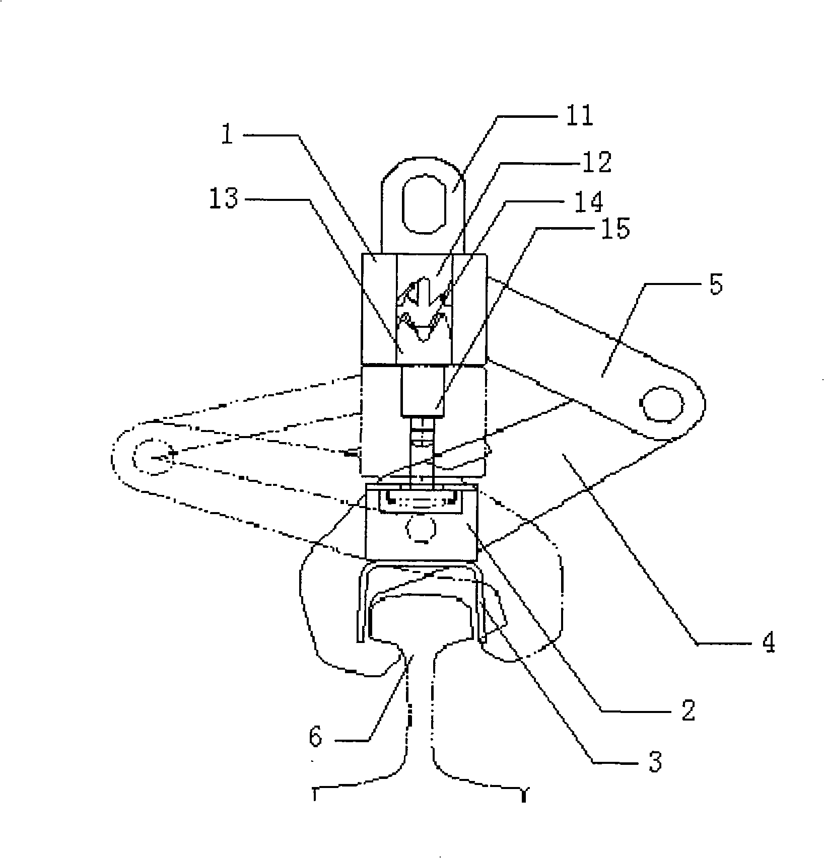
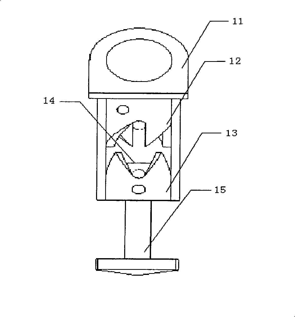
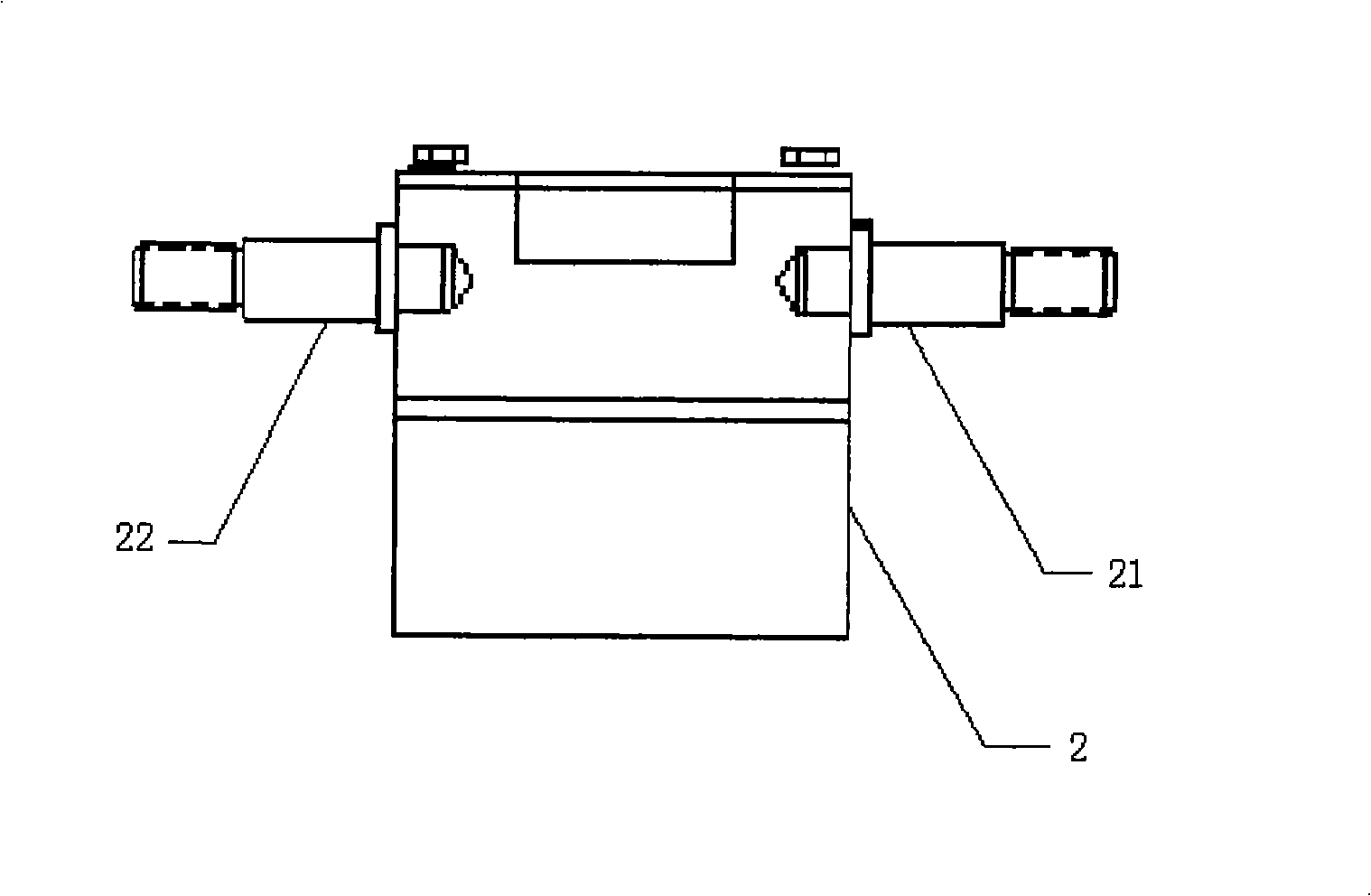
[0021] Below in conjunction with accompanying drawing, the present invention is described in further detail:

[0022] The device is composed of a hook base 1, a suspension base 2, a guide plate 3, a clamp arm 4, and a connecting rod 5. The hook base 1 is composed of a lug plate 11, an upper gear ring 12, a lower gear gear 13, a screw rod 14, and a T-shaped hook 15. , A first shaft 21 and a second shaft 22 are arranged on the suspension base 2 . The clamp arm 4 is connected with the suspension base 2 through the first shaft 21 and the second shaft 22 on the suspension base 2. The clamp arm is used to grasp and clamp the rail 6. One end of the connecting rod 5 is connected with the hook base 1 through the shaft, and the other end The shaft is connected to the clamp arm 4, and the connecting rod 5 is connected to the clamp arm 4 to form a four-link structure. The four-link displacement is driven by the up and down movement of the hook base 1, so that the clamp arm 4 only needs to...


PUM


Abstract

The present invention discloses a mechanical type automatic catching and laying rail device, consisting of a hook seat, a hanging seat, a guide board, a clamping arm, and a link lever, wherein the hook seat consists of a hanging lug board, an upper gear ring, a lower gear ring, a screw rod, and a T-shaped hook, wherein the clamping arm is connected with the hanging seat by an axle on the hanging seat; one end of the link lever is connected with the hook seat by the axle, while the other end is connected with the clamping arm by the axle; the link lever is connected with the clamping arm to form a four-bar linkage structure; the four link levers are driven to displace by the upward and downward movement of the hook seat so as to open or close the clamping arm and achieve the steel rail catching movement and the steel rail laying movement; the upper gear ring is fixed in the hook seat, while the lower gear ring can be rotated along with the upward movement and the downward movement of the T-shaped hook; the mechanical self-locking and unlocking is realized by the rotation of the lower gear ring and the separation and joggling of the upper gear ring. The device does not need the drive of a power source, and is not restricted by the work environment. Just by the mechanical movement, automatic rail catching and laying can be realized. The device is simple in structure, convenient in operation, practical, reliable, lower in cost, high in economy, and high in practicability.

Description

technical field [0001] The invention relates to a spreader mounted on a crane, more particularly to a mechanical automatic rail grabbing and releasing device, especially suitable for self-hoisting of railway rails. Background technique [0002] Long rail products are processed and produced in rail welding factories (or rail welding bases). The production process of long rails in my country includes: lifting and unloading of welding rails, sorting and storing rails, and welding rails. At present, the hoisting equipment used by the rail welding factories of various railway bureaus in my country is still quite simple. Only one electric hoist is installed every 16 meters. For example, 32 electric hoists are required for hoisting a 500-meter long rail. One operator, holding the button and coordinating with adjacent personnel for hoisting, the hoisting hook still relies on manual work, especially the operation efficiency of installing the 500-meter-long steel rail on the long rail ...

Claims


Application Information

Patent Timeline
IPC IPC(8): B66C1/10B66C1/42B66C1/64
Inventor 应志军俞得胜谢鹏
Owner 武汉凯盟机电工程有限公司
Why Eureka
Try Eureka