Dust collection structure

A technology of dust collection bucket and dust collection chamber, which is applied in the direction of suction filter, etc., can solve the problems of increased air turbidity and increased filter workload, and achieve the effect of increased workload

Inactive Publication Date: 2008-12-31
LG ELECTRONICS (TIANJIN) APPLIANCES CO LTD
View PDF0 Cites 4 Cited by
  • Summary
  • Abstract
  • Description
  • Claims
  • Application Information

AI Technical Summary

Problems solved by technology

[0009] In the prior art, the inner wall of the dust collecting barrel is smooth, and the sucked air forms a swirling airflow that rotates downward in the barrel cavity, blowing up the dust that has settled to the bottom of the barrel, and increasing the turbidity of the air that needs to be filtered. thus increasing the workload of the filter

Method used


Image

  • Dust collection structure
  • Dust collection structure
  • Dust collection structure

Examples


Embodiment Construction

[0022] In order to further understand the invention content, characteristics and effects of the present invention, the following examples are given, and detailed descriptions are as follows in conjunction with the accompanying drawings:

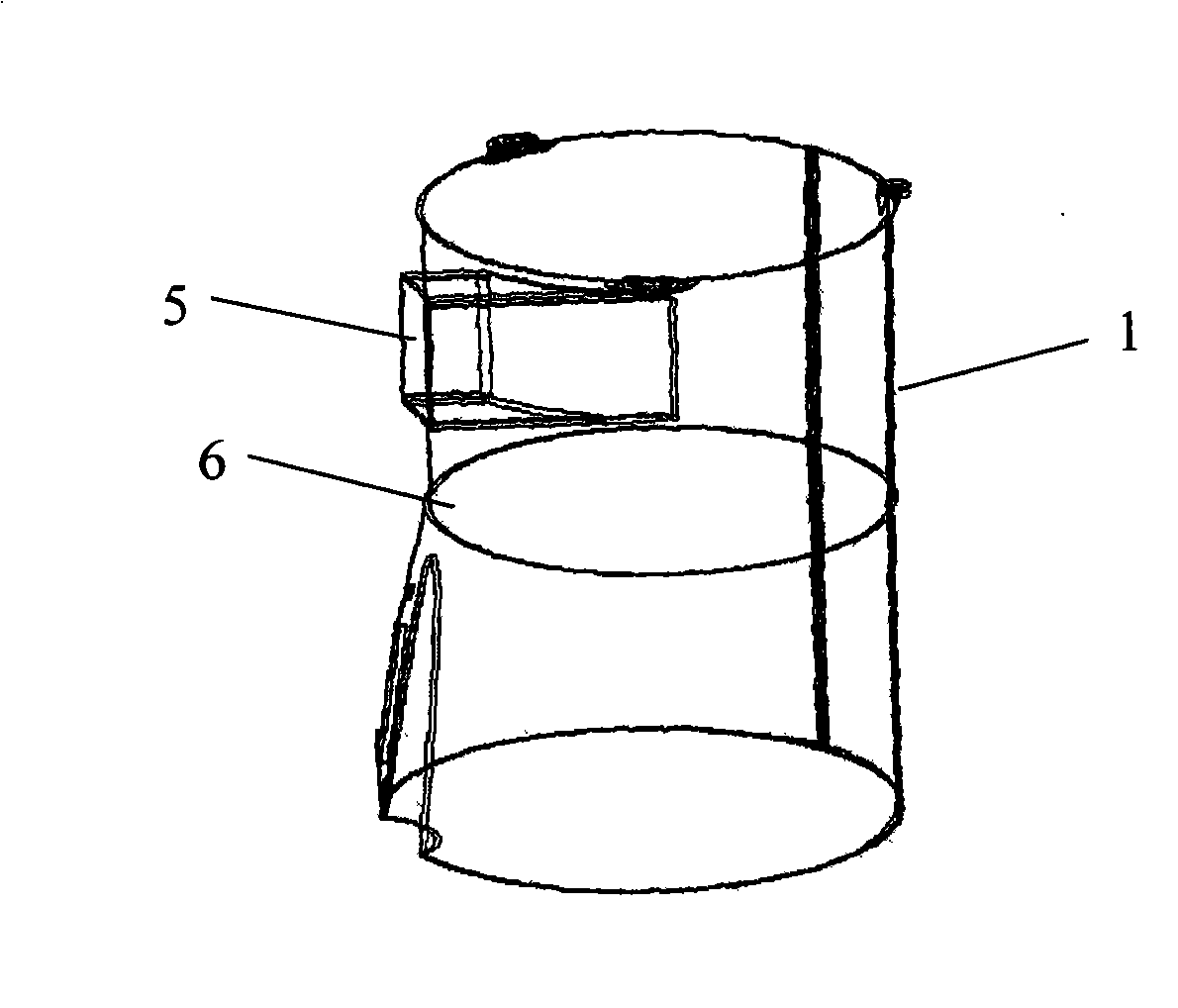
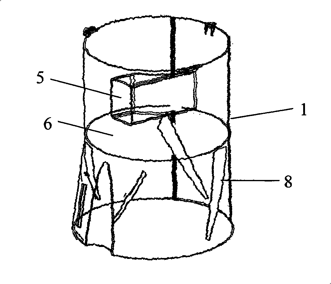
[0023] image 3 It is a three-dimensional schematic diagram of the bucket body of the dust collecting bucket of the present invention.

[0024] In the drawings, the same symbols are used for the same components.

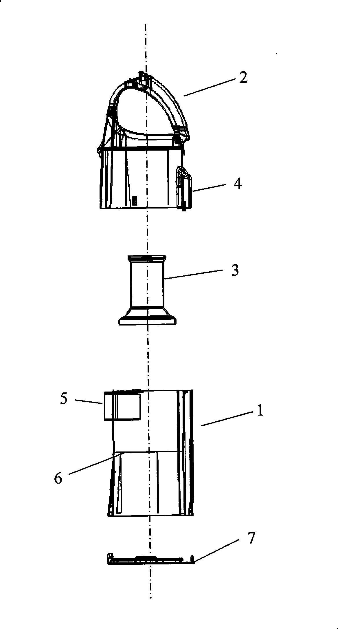
[0025] Such as image 3 As shown, a dust collecting barrel structure, the dust collecting barrel includes a barrel body 1; an upper cover 2; and a filter 3 including a filter cover and a filter element; a bottom cover 7 hingedly formed at the bottom of the barrel; the dust collecting barrel barrel 1 A plurality of windshields 8 that can change the direction of the airflow are formed in the lower dust collection chamber; a plurality of windshields 8 that can change the direction of the airflow are formed in the dust collection cham...


PUM


Abstract

The invention discloses dust barrel structure and the dust barrel comprises a barrel body, an upper cover, a filter including a filtration cover and a filtration core, a bottom cover which is articulately formed in the bottom part of the barrel body and a plurality of windshield tablets which can change the air flow directions and are formed in the dust cavity of the lower part of the dust barrel body. For the windshield tablets are formed in the dust cavity in the lower part of the dust barrel body, when the ingulfed air forms a rotating airflow and rotate in the dust cavity of the barrel body, due to the influences of the windshield tablets, the air flow rotates upwards to reduce the dust which settles down at the bottom of the barrel body and the air flow blows again, thus the working amount of the filter is increased.

Description

technical field [0001] The invention belongs to a dust collecting and filtering device for a vacuum cleaner, in particular to a structure of a dust collecting barrel for changing the airflow direction. Background technique [0002] Vacuum cleaner is a kind of household appliance for indoor cleaning and sanitation, which is used to remove dust from floors, carpets, walls, furniture, clothing and various gaps. Generally speaking, a vacuum cleaner mainly includes a suction device and a suction pipeline. The suction device mainly formed by a motor and a fan is arranged in the body. The suction pipeline includes a suction head and a suction pipe. The air port communicates with the air inlet of the fan inside the body through the telescopic pipe and flexible pipe of the suction pipe. When the vacuum cleaner is running, the motor drives the impeller of the fan to rotate at a high speed, exhausting the air inside the vacuum cleaner, forming an instantaneous vacuum inside the vacuum...

Claims


Application Information

Patent Timeline
IPC IPC(8): A47L9/12A47L9/10
Inventor 刘庆林
Owner LG ELECTRONICS (TIANJIN) APPLIANCES CO LTD
Why Eureka
Try Eureka