Paint supply system

A coating supply and coating technology, applied in the direction of spraying devices, liquid spraying devices, etc., can solve problems such as paint clogging, complicated cleaning operations, and increased equipment costs

Inactive Publication Date: 2008-12-31
HONDA MOTOR CO LTD
View PDF2 Cites 6 Cited by
  • Summary
  • Abstract
  • Description
  • Claims
  • Application Information

AI Technical Summary

Problems solved by technology

[0006] However, in the technology of the above-mentioned Patent Document 1, there is such a disadvantage that since the paint cutoff valve seat of the fluid switch assembly of the closed circulation pipe is located on the side of the manifold that enters the inner side of the circulation pipe, and there is a gap between the circulation pipe and the paint. There is a passage of a certain length formed between the shut-off valve seats, so the highly viscous paint waste peeled off by the pig enters the passage of a certain length to block the paint
[0007] In addition, in the technology of Patent Document 2, there is such a problem that when it is intended to apply this technology to a device structure in which circulation piping is separately installed according to spraying colors, it is necessary to install pig stations in each of the plurality of circulation piping. or pigs, so equipment costs are higher
In addition, there is also the problem that if the path between the paint tank and the circulation piping that the pig does not pass is long, the path needs to be cleaned, and if an additional cleaning mechanism is required, the structure of the device will become complicated, and the cleaning work will be complicated. also become complicated

Method used


Image

  • Paint supply system
  • Paint supply system
  • Paint supply system

Examples


Embodiment Construction

[0024] Embodiments of the present invention will be described below based on the drawings.

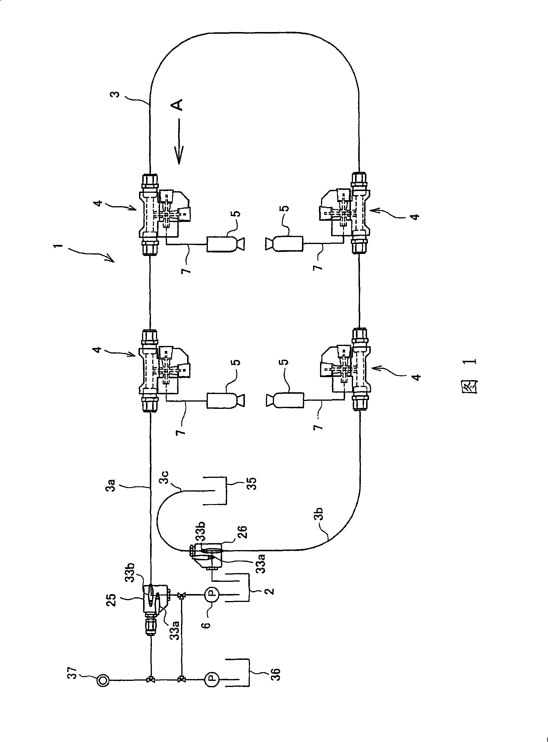
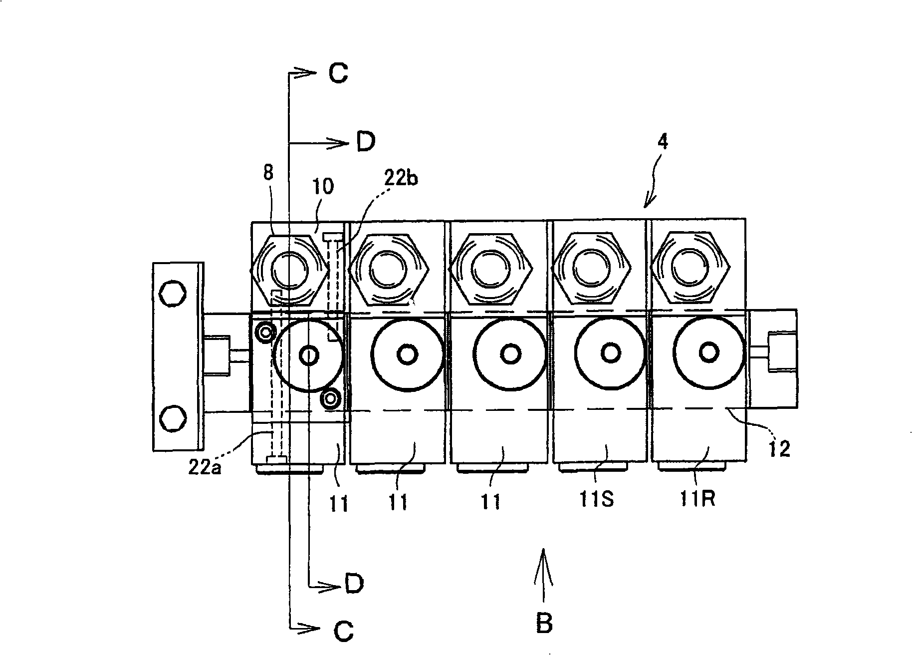
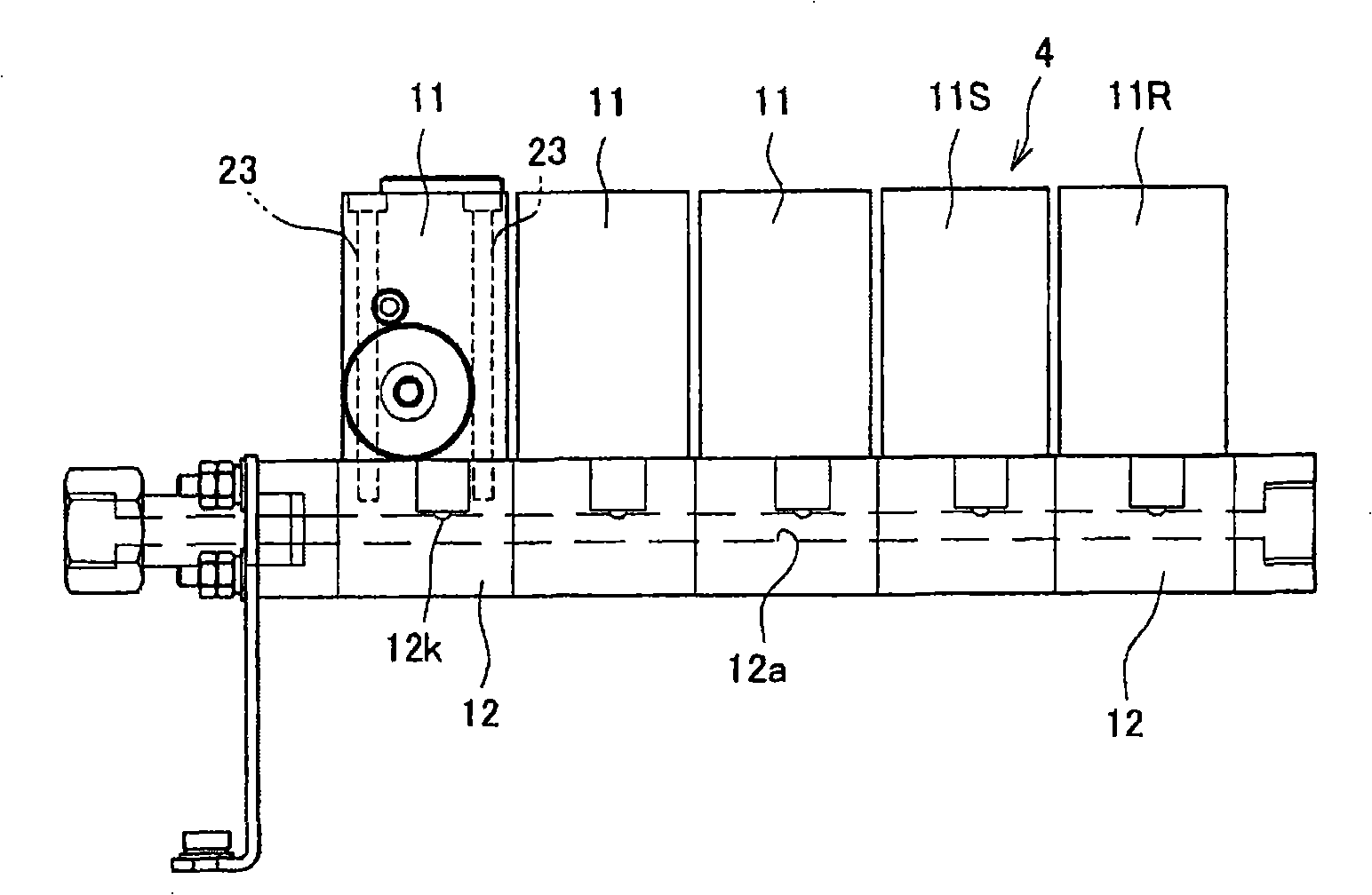
[0025] Here, Fig. 1 is a schematic structural view showing the circulation piping of a certain color paint of the paint supply device of the present invention, figure 2 It is an explanatory diagram of the color change valve viewed from the direction A of Fig. 1, image 3 From figure 2 The explanatory diagram viewed in the direction of B, Figure 4 is figure 2 The C-C line profile, Figure 5 is figure 2 Figure 6 and Figure 7 are explanatory diagrams for putting the pig into the valve.

[0026] The paint supply device of the present invention is constituted, for example, as a device for supplying paint to a spray gun in a spray booth used in an automobile body spray process, so that a plurality of paint cycles installed from the paint mixing room to the spray booth are cleaned with a pig. During piping, it is difficult to clog the paint passage with peeled deposits, and it is possible ...


PUM


Abstract

To prevent a paint passage from being clogged with exfoliated deposits even when a paint piping on the like is cleaned with a pig, and to perform cleaning of substantially entire region of circulation piping efficiently and surely. In a paint supply system (1) where color change valves (4) are connected to the middle of closed loop paint circulation piping (3) extending from a paint tank (2) and returning to the paint tank (2) and a paint gun (5) is connected with each color change valve (4), a pig charging valve (25) is provided at that position on the upstream side of paint circulation pipings (7) where a pig (27) can be charged linearly and it is closest to a paint pressure feed pump (6), and a pig discharging valve (26) is provided at that position on the downstream side of the circulation pipings (7) where a pig (27) can be discharged linearly and it is closest to the paint tank (2). A first opening (10k) on the upstream side of the color change valve (4) is provided at a position close to the inner wall of a through hole (h) constituted as a part of the circulation piping (3) such that no space is allowed between the inner wall and the first opening (10k).

Description

technical field [0001] The present invention provides a paint supply device, and particularly relates to a technique such as, among paints of various colors supplied from a plurality of paint supply sources, selecting paint of a desired color and feeding it into a paint supply device of a paint spray gun , can reliably clean the inner wall of the closed-loop paint circulation pipe connected to the paint supply source. Background technique [0002] At present, a technique is widely used in the body painting process of automobiles, that is, a plurality of painting robots having painting guns are installed in a painting room, and paint is supplied to the painting guns by a paint supply device. As such a paint supply device, paint tanks of various colors are installed in the paint mixing room, and closed-loop paint circulation pipes are connected to each paint tank to form a circuit that can circulate and supply to the spray booth. Connect the color change valve that can switch...

Claims


Application Information

Patent Timeline
Patent Type & Authority Applications(China)
IPC IPC(8): B05B12/14
CPCB05B9/0423B05B12/1481B05B12/14
Inventor 竹口弘孝驹田都尚铃木润一
Owner HONDA MOTOR CO LTD
Why Eureka
Try Eureka