Cleaning structure of industry parts washer

A technology for cleaning warehouses and washing machines, which is applied in the directions of cleaning methods, cleaning methods and utensils, chemical instruments and methods using liquids, etc., which can solve the problems of unsafe working conditions, increase labor intensity, flammability, etc., and improve cleaning efficiency. Effect

Inactive Publication Date: 2009-01-07
田飞
View PDF0 Cites 6 Cited by
  • Summary
  • Abstract
  • Description
  • Claims
  • Application Information

AI Technical Summary

Problems solved by technology

[0002] The cleaning chamber of the existing industrial parts cleaning machine generally adopts a non-closed system, and it is necessary to manually use gasoline, kerosene and alkaline solution as the cleaning liquid to clean and oil seal the industrial parts, so that workers need to directly contact the cleaning machine during its operation. Cleaning agent, and the organic solvent used is extremely volatile, resulting in waste of solvent, pollution to the environment, and easy to cause harm to the human body, and it will also bring problems of flammability, unsafe and poor working conditions, and increase labor intensity

Method used


Image

  • Cleaning structure of industry parts washer
  • Cleaning structure of industry parts washer
  • Cleaning structure of industry parts washer

Examples


Embodiment Construction

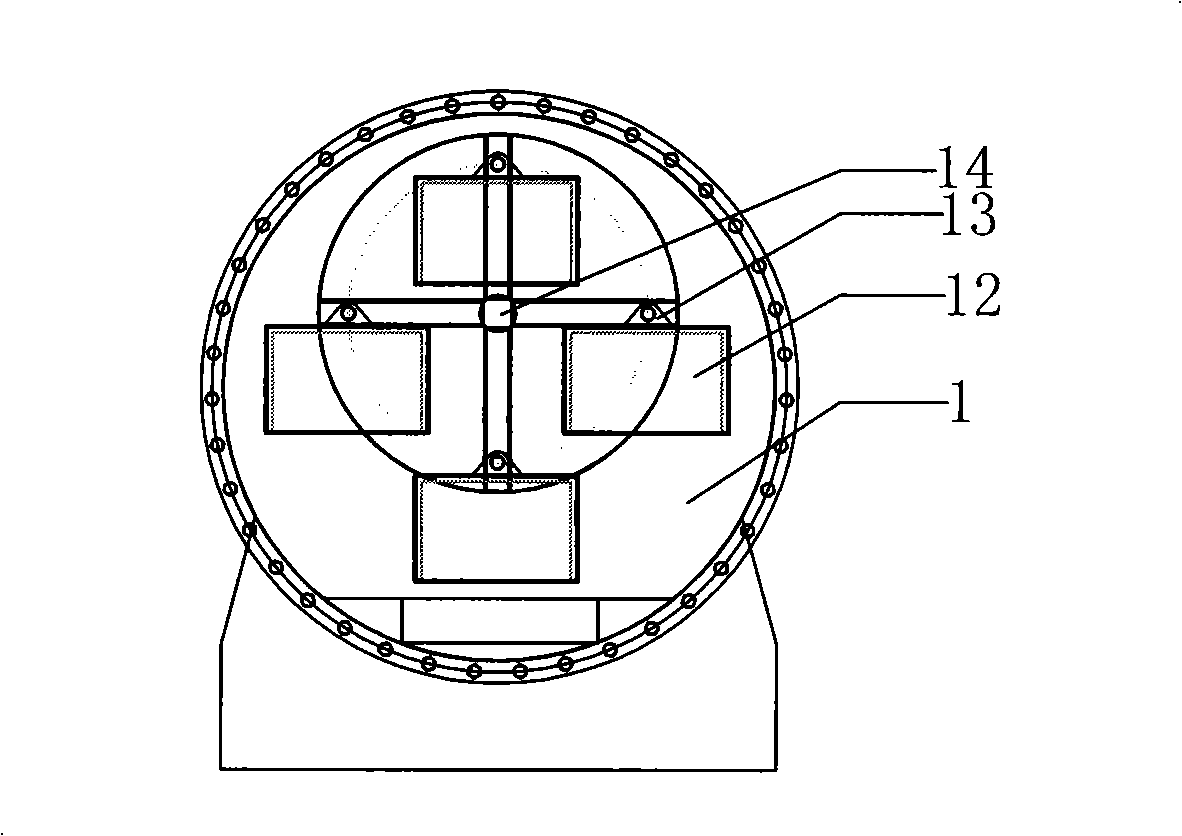
[0012] like figure 1 As shown, the cleaning chamber structure of the industrial parts cleaning machine described in the utility model is a cleaning chamber structure of an industrial parts cleaning machine. The cleaning chamber 1 is a cylinder, and several hanging baskets 12 for loading parts are installed in the cleaning chamber 1. The hanging basket 12 is hung on the hanging basket support 13, and the hanging basket support 13 is equipped with an eccentric main shaft 14 relative to the cylindrical cleaning chamber 1, which is driven to rotate by the main transmission system 2 with a reducer; the hanging basket support 13 can be rotated clockwise or Turn counterclockwise.

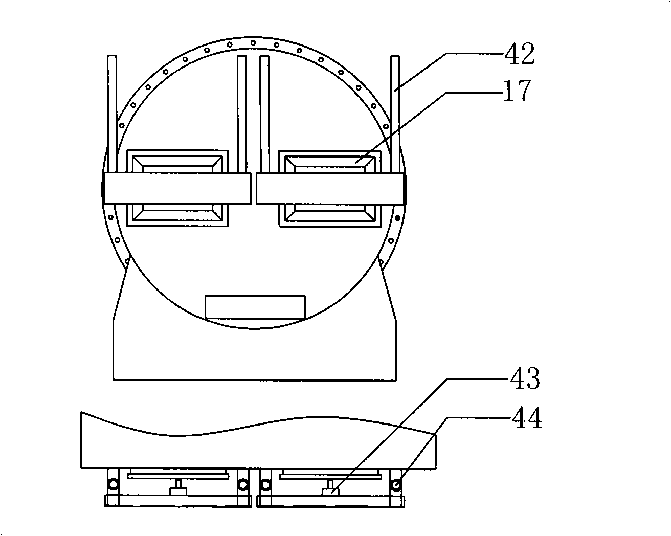
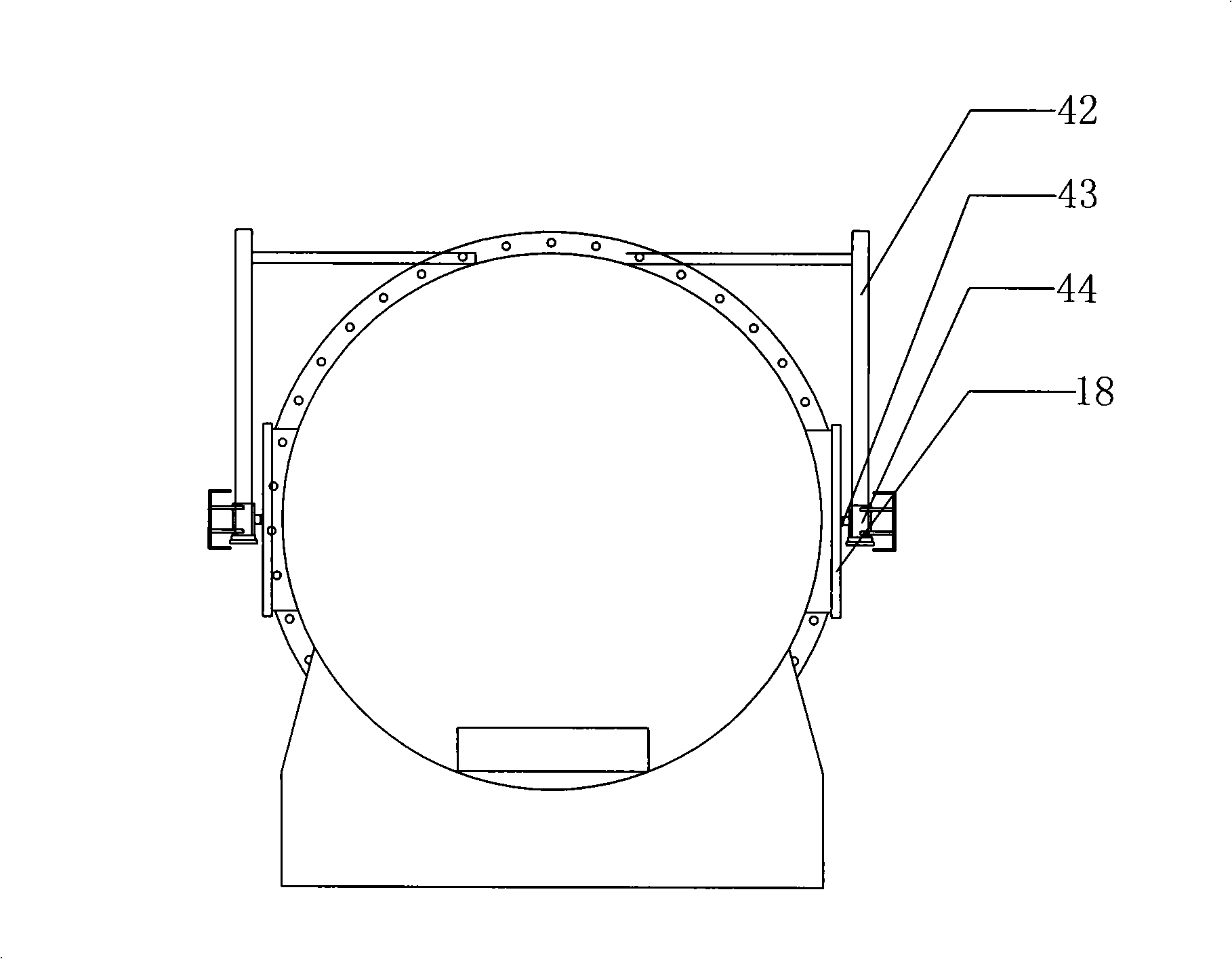
[0013] like Figure 2-3 As shown, there are two ways to open the door of the cleaning chamber of the industrial parts cleaning machine described in the utility model: one is to open two door 17 horizontally on the cylindrical end surface of the cleaning chamber 1, and the door 17 is opened by the cylinder...


PUM


Abstract

The invention relates to a cleaning bin structure for an industrial component cleaning machine. The cleaning bin is cylindrical; a hanging basket charged with a plurality of components is mounted in the cleaning bin, and suspended on a hanging basket support; the hanging basket support is provided with an eccentric main shaft relative to the cylindrical cleaning bin; the main shaft is driven by a main transmission system provided with a speed reducer to rotate; the hanging basket support can rotate clockwise or anticlockwise; two bin gates are formed in the following two ways: firstly, the two bin gates are horizontally formed on the cylindrical end surface of the cleaning bin; secondly; the two bin gates are horizontally formed on the cylindrical side surface of the cleaning bin. The cleaning bin structure has the advantages that the two bin gates of the cleaning bin can be used for assembling and disassembling the components simultaneously, thereby realizing cycle-cleaning operation, and enhancing the cleaning efficiency.

Description

technical field [0001] The invention relates to the field of industrial parts cleaning equipment, in particular to a cleaning chamber structure of an industrial parts cleaning machine. Background technique [0002] The cleaning chamber of the existing industrial parts cleaning machine generally adopts a non-closed system, and it is necessary to manually use gasoline, kerosene and alkaline solution as the cleaning liquid to clean and oil seal the industrial parts, so that workers need to directly contact the cleaning machine during its operation. Cleaning agent, and the organic solvent used is extremely volatile, resulting in waste of solvent, pollution to the environment, and easy to cause harm to the human body, and also brings about problems of flammability, unsafe and poor working conditions, and increased labor intensity. Contents of the invention [0003] The purpose of the present invention is to provide a cleaning chamber structure of an industrial parts cleaning ma...

Claims


Application Information

Patent Timeline
Patent Type & Authority Applications(China)
IPC IPC(8): B08B3/04
Inventor 田飞
Owner 田飞
Why Eureka
Try Eureka