
Liquid material conveying device

A technology for conveying devices and liquid materials, which is applied in liquid cleaning methods, gas/liquid distribution and storage, and cleaning of hollow objects, etc. It can solve the problems of large waste water, time-consuming and expensive cleaning of pipelines, etc.

Pending Publication Date: 2020-03-24
SICHUAN GOLDEN ELEPHANT SINCERITY CHEM CO LTD +1
View PDF0 Cites 0 Cited by
  • Summary
  • Abstract
  • Description
  • Claims
  • Application Information

AI Technical Summary

Problems solved by technology

As can be seen from the above, once the pipeline is blocked, it will take a lot of time and money to clean the pipeline
[0004] In order to solve the above problems, in some technologies, steam or hot water is used to directly contact urea, and the urea is dissolved in water to achieve the purpose of cleaning the pipeline, but this method will generate a large amount of waste water

Method used


Image

  • Liquid material conveying device
  • Liquid material conveying device
  • Liquid material conveying device

Examples


Embodiment

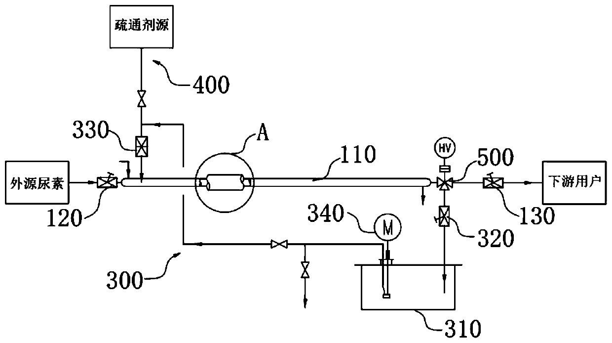
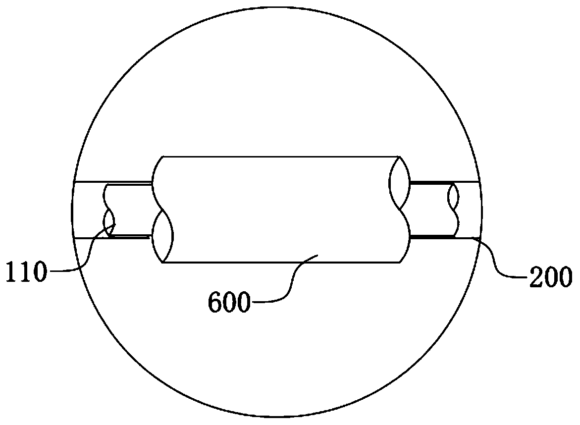
[0038] This embodiment provides a liquid material conveying device, such as figure 1 and figure 2 As shown, the liquid material conveying device includes a main delivery pipe 110, a jacket pipe 200 and a cleaning branch 300; the main delivery pipe 110 is provided with a start valve 120 and an end valve 130; , and an annular cavity for introducing a heat source is formed between the jacket pipe 200 and the main delivery pipe 110. The heat source in the annular cavity can exchange heat with the liquid material in the main delivery pipe 110. One end of the annular cavity It has an inlet and the other end has an outlet; the cleaning branch 300 is provided with a liquid storage tank 310, and both ends of the cleaning branch 300 are connected to the main delivery pipe 110 between the start valve 120 and the end valve 130, and the cleaning branch 300 and the main delivery pipe 110 can form a circulation loop, and the circulation loop is provided with power elements for providing po...


PUM


Abstract

The invention provides a liquid material conveying device, and relates to the technical field of chemical machinery. The liquid material conveying device comprises a main feeding pipe, a clamping sleeve and a cleaning branch; a starting end valve and a tail end valve are arranged on the main feeding pipe; the clamping sleeve sleeves the outer side of the main feeding pipe, an annular cavity is formed between the clamping sleeve and the main feeding pipe, one end of the annular cavity is provided with an inlet, and the other end of the annular cavity is provided with an outlet; and a liquid storage groove is formed in the cleaning branch, the two ends of the cleaning branch are connected to the main feeding pipe between the starting end valve and the tail end valve, the cleaning branch andthe main feeding pipe can form a circulation loop, the circulating loop is provided with a power element for providing power for mixed liquid flow, the technical problem that a large amount of wastewater is generated in the urea pipeline cleaning mode in the prior art is relieved, and the technical effect of reducing the waste water displacement is achieved.

Description

technical field [0001] The invention relates to the technical field of chemical machinery, in particular to a liquid material conveying device. Background technique [0002] In some chemical production installations, such as urea installations and melamine installations, pipelines are required to transport liquid urea. Among them, the melting point of urea is 132.7°C. Under normal production conditions, the temperature in the entire pipeline must be kept above the melting point. However, since the outside temperature is significantly lower than the melting point of urea, urea is solid at room temperature, which inevitably brings about a common problem, that is, if some urea remains in the delivery pipeline after the production device stops running, the urea will gradually Cool and set. [0003] In some technologies, opaque metal pipes are used for urea pipelines, so it is difficult to judge whether there is a blockage. When the pipeline is used next time, the delivery of ...

Claims


Application Information

Patent Timeline
IPC IPC(8): B08B9/027F17D1/18
CPCB08B9/027F17D1/18B08B2203/007
Inventor 唐印龚元德宋国天孔德利杨秀珍
Owner SICHUAN GOLDEN ELEPHANT SINCERITY CHEM CO LTD
Learn More