
Autostereoscopic display device

A technology for displaying pixels and display panels, which is applied in stereoscopic systems, image communications, electrical components, etc., and can solve problems such as inability to provide stereoscopic images and loss of resolution

Active Publication Date: 2012-06-20
KONINK PHILIPS ELECTRONICS NV
View PDF2 Cites 0 Cited by
  • Summary
  • Abstract
  • Description
  • Claims
  • Application Information

AI Technical Summary

Problems solved by technology

2D display modes of course do not provide stereoscopic images
The resulting display can provide stereoscopic images, but also suffers from the unavoidable loss of resolution described above

Method used


Image

  • Autostereoscopic display device
  • Autostereoscopic display device
  • Autostereoscopic display device

Examples


Embodiment Construction

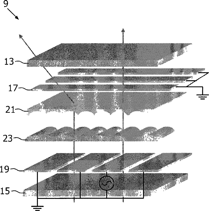
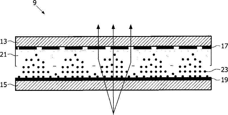
[0030] The present invention provides a display device having a display area switchable between a two-dimensional display mode and a three-dimensional display mode. Switching between modes is achieved by applying an electric field to an array of lens elements formed from liquid crystal material. In 2D, the lens elements behave as if they were a sheet of ordinary transparent material. In three-dimensional mode, the lens elements provide a light output function to enable viewing of stereoscopic images. An electric field is applied across the lens element using an electrode layer spaced from the lens element. The spacing of the electrode layer from the lens element improves the stability of the electric field within the lens element.

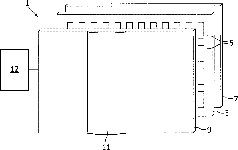
[0031] figure 1 is a schematic perspective view of a known switchable autostereoscopic display device to which the present invention can be applied. The display device 1 is shown in expanded form.

[0032] The known device 1 comprises a liquid...


PUM


Abstract

A lenticular element arrangement (31) includes: a lens array (23) for guiding the light output, the lens array (23) including an electro-optic material of which an refractive index is switchable by selective application of an electric field between a first value that maintains the light output directing function and a second value that removes the light output directing function; and electrode arrangements (17, 19, 35) provided above and below the lens elements (23) for applying the electric field across the lens elements, wherein at least one of the electrode arrangements comprises first and second electrode layers (19, 35) separated by a dielectric layer (33), each electrode layer (19, 35) comprising a plurality of electrodes separated by gaps, the electrodes of each electrode layer (19, 35) being aligned with the gaps of the other electrode layer (19, 35), such that the effect of the gaps on the electric field in the lens elements (23) is reduced. A switchable autostereoscopic display device comprises: a display panel having an array of display pixels for producing a display, the display pixels being arranged in rows and columns; and the lenticular element arrangement (31) arranged according to the invention over the display panel for directing the light output of the display pixels so as to provide a stereoscopic image,

Description

technical field [0001] The invention relates to a lenticular element structure, and a type of autostereoscopic display device comprising a display panel having an array of display pixels for producing a display and said lenticular element structure. Background technique [0002] A known autostereoscopic display device is disclosed in GB2196166A. Known devices include a two-dimensional liquid crystal display panel with a row and column array of display pixels acting as a spatial light modulator to produce the display. An array of elongated lens elements extending parallel to each other overlies the display pixel array and the display pixels are viewable through these lens elements. The lens elements are sheet elements, each element comprising an elongated semi-cylindrical lens element. The lenticular elements are elongated in the column direction of the display panel, each lenticular element covering a respective group of display pixels of two or more adjacent columns. [...

Claims


Application Information

Patent Timeline
Patent Type & Authority Patents(China)
IPC IPC(8): H04N13/00
Inventor M·G·H·希丁克S·T·德兹沃特O·H·威廉森
Owner KONINK PHILIPS ELECTRONICS NV
Learn More